
Liquid container and method of manufacturing the same

a technology of liquid containers and liquid droplets, which is applied in the direction of manufacturing tools, water supply installations, drawing-off water installations, etc., can solve the problems of ink corresponding to the margin remaining in some apparatuses, the head may eject ink droplets with non-uniform weight, and complicating the sealing structure of the electrode, so as to enhance the liquid detection precision

Active Publication Date: 2009-12-31
SEIKO EPSON CORP
View PDF5 Cites 30 Cited by
  • Summary
  • Abstract
  • Description
  • Claims
  • Application Information

AI Technical Summary

Benefits of technology

[0016]An advantage of some aspects of the invention is that it provides a liquid container that can prevent formation of bubbles in the immediate upstream of a sensor cavity even when the amount of remaining ink decreases, thereby enhancing the liquid detection precision.
[0017]Another advantage of some aspects of the invention is that it provides a liquid container that can reduce the false detection by employing a structure for enhancing the amplitude at the time of detecting the liquid and a structure for suppressing bubbles from staying around the sensor base at the time of introducing the liquid.
[0018]Another advantage of some aspects of the invention is that it provides a method of manufacturing a liquid container that can deliver bubbles to satisfactorily fill the liquid container with the liquid even when the bubbles are easily gathered due to its structure at the time of filling the liquid container with the liquid.

Problems solved by technology

However, the method of managing the ink consumption by integrating the number of ejected ink droplets or the amount of ink by software causes the following problem.
The head may eject ink droplets with non-uniformity in weight.
Accordingly, there is a problem that the ink corresponding to the margin remains in some apparatuses.
However, since the detection of the ink level depends on the conductivity of the ink, the kinds of ink detectable are limited, thereby complicating the sealing structure of the electrode.
Since two electrodes should be necessarily formed, the number of manufacturing processes increases, thereby increasing the manufacturing cost.
In the technique disclosed in JP-A-2006-315302, the vibration of the piezoelectric element is absorbed by the main case coming in contact with the sensor base at three positions, thereby making it difficult to satisfactorily guarantee the vibration being detectable by the piezoelectric element.
Since the sensor base is positioned in an opening formed in the main case, bubbles may stay in minute gaps around the sensor base at the time of injecting the ink, thereby causing false detection of the ink end.

Method used


Image

  • Liquid container and method of manufacturing the same
  • Liquid container and method of manufacturing the same
  • Liquid container and method of manufacturing the same

Examples


modified example

[0113]Although this embodiment has been described in detail, it should be understood by those skilled in the art that the embodiment can be modified in various forms without departing from the idea and advantages of the invention. Therefore, the following modified examples should be included in the scope of the invention. For example, in the specification or drawings, a term described at least once along with another term having broader meaning or equivalent meaning can be replaced with the another term in any place of the specification or drawings.

[0114]As shown in FIGS. 14A and 14B, the partition wall 136 may have a shape in which the thickness of the free end 136b is smaller than that of the base portion 136a close to the channel wall 102a. That is, even when the base portion 136a is broader than the inter-edge distance of the first and second holes 212 and 214, it does not cause any problem so long as the thickness of the free end 136b is equal to or less than the inter-edge dis...


PUM

PropertyMeasurementUnit
Timeaaaaaaaaaa
Areaaaaaaaaaaa
Depthaaaaaaaaaa

Abstract

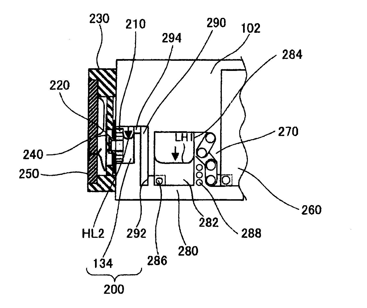
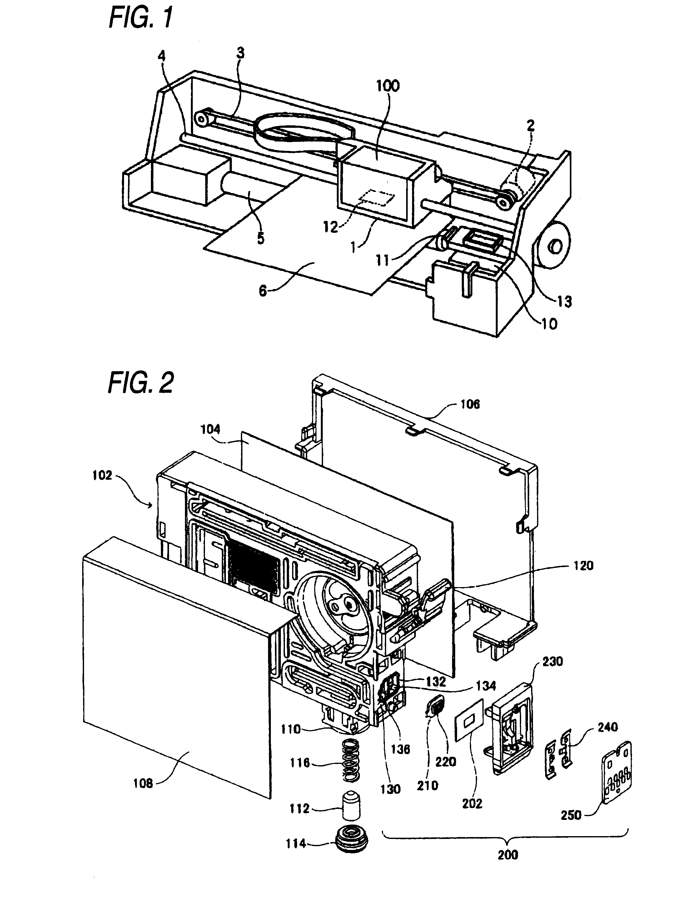
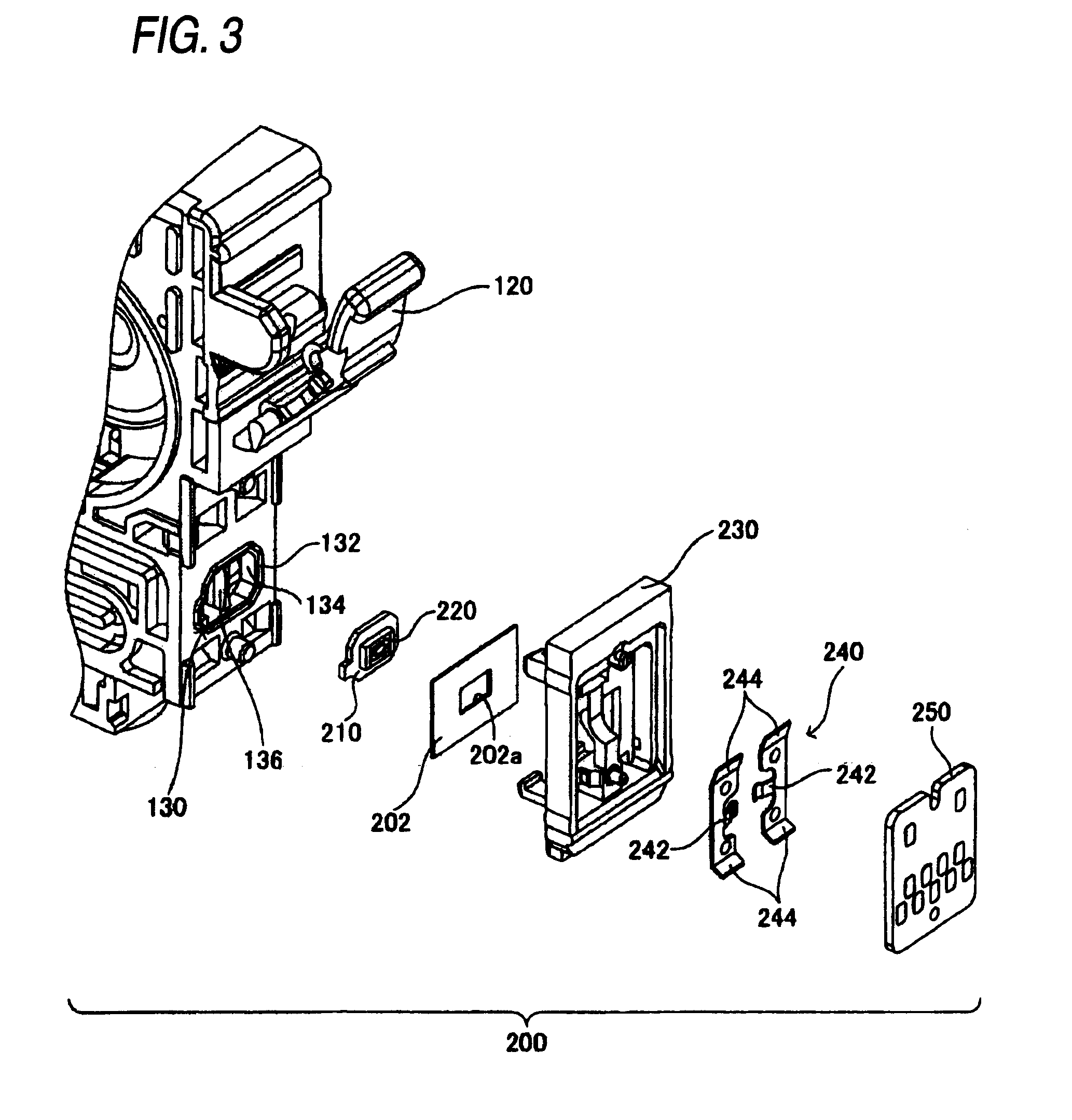
A liquid container includes: a case in which a flow channel of a liquid is exposed from an opening; a sensor base, disposed in the opening of the case to face the flow channel; a sensor chip, including: a piezoelectric element, mounted on a surface opposite to a surface of the sensor base which faces the flow channel; and a sensor cavity, disposed opposite to the piezoelectric element and adapted to receive the liquid as a detection target; a film, adapted to hold the sensor base in the opening and sealing the opening; a partition wall, partitioning the flow channel in the case into an upstream buffer chamber and a downstream buffer chamber; and a bubble trapping section, disposed upstream of the upstream buffer chamber. The bubble trapping section includes: a bubble trapping chamber, adapted to trap bubbles upside by allowing the liquid level to be lowered with reduction in an amount of remaining liquid at a time of consuming the liquid; an inlet, communicating at a vertical upper position of the bubble trapping chamber to introduce the liquid at the time of consuming the liquid; and an outlet, communicating at a vertical lower position of the bubble trapping chamber to discharge the liquid at the time of consuming the liquid.

Description

BACKGROUND[0001]1. Technical Field[0002]The present invention relates to a liquid container suitable for detecting an amount of remaining liquid (ink) in a liquid consuming apparatus such as an inkjet printing apparatus and a method of manufacturing the liquid container.[0003]2. Related Art[0004]As a representative example of a liquid consuming apparatus, there is an inkjet printing apparatus having an inkjet print head for printing an image. Other liquid ejecting apparatuses may include an apparatus having a coloring material ejecting head used for manufacturing a color filter and the like of a liquid crystal display, an apparatus having an electrode material (conductive paste) ejecting head used for forming electrodes of an organic EL display, a field emission display (FED), and the like, an apparatus having a biological organic material ejecting head used for manufacturing a bio chip, and an apparatus having a sample ejecting head as a precise pipette.[0005]In the inkjet printing...

Claims


Application Information

Patent Timeline
IPC IPC(8): B41J2/19B23P11/00
CPCB41J2/17559B41J2/17566B41J2002/17583B41J2002/17579B41J2/19Y10T137/0402
Inventor WANIBE, AKIHISA
Owner SEIKO EPSON CORP
Learn More