
Duplex tab exhaust nozzle

a technology of exhaust nozzle and double tabs, which is applied in the direction of marine propulsion, vessel construction, aircraft navigation control, etc., can solve the problems of reducing engine efficiency or performance, corresponding additional weight in the aircraft, and high-speed core and fan exhaust streams generating noise, so as to achieve effective noise attenuation and minimize engine performance and efficiency losses.

Active Publication Date: 2009-12-31
GENERAL ELECTRIC CO
View PDF40 Cites 15 Cited by
  • Summary
  • Abstract
  • Description
  • Claims
  • Application Information

AI Technical Summary

Benefits of technology

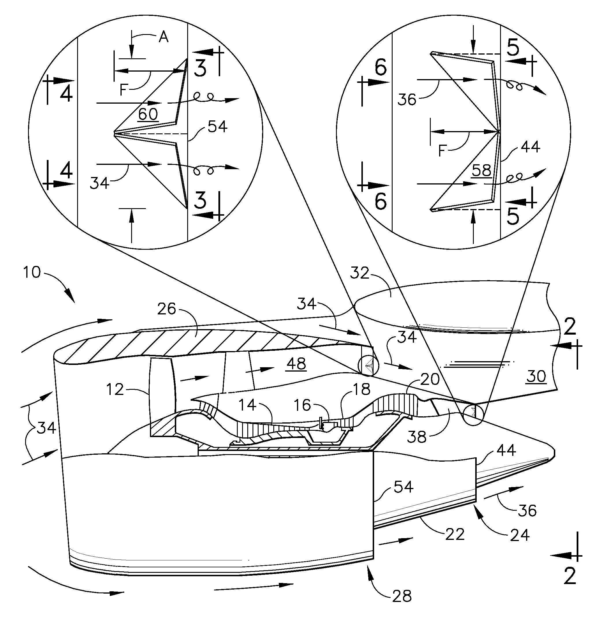
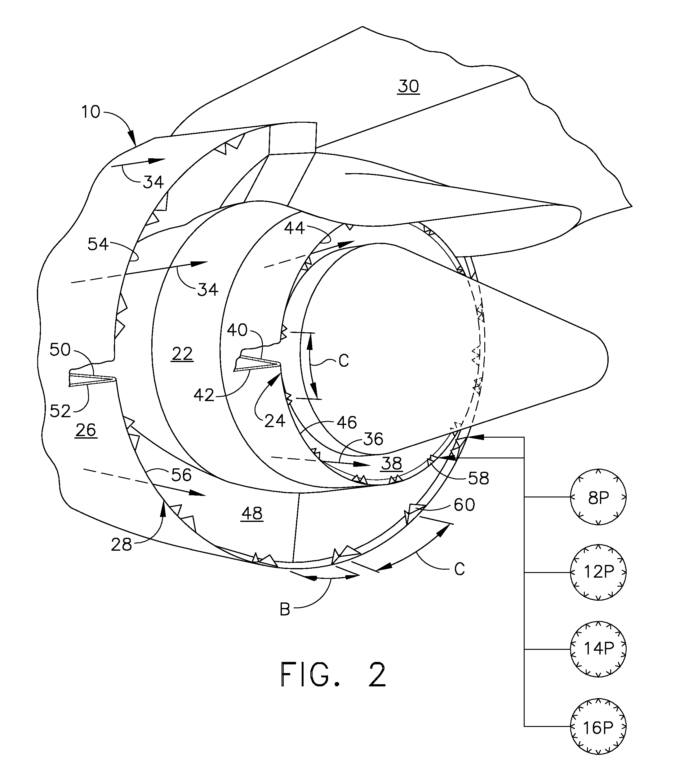
[0009]An exhaust nozzle includes a duct terminating in an outlet. A row of vortex generating duplex tabs are mounted in the outlet. The tabs have compound radial and circumferential aft inclination inside the outlet for generating streamwise vortices for attenuating exhaust noise while reducing performance loss.

Problems solved by technology

The high velocity core and fan exhaust streams generate noise during operation, which is a particular problem during aircraft takeoff at high power which is in contrast with aircraft cruise at high altitude at correspondingly lower power output where noise is less of a problem but maximum engine efficiency is desired.
Noise attenuation mechanisms have been investigated for decades, but all have associated problems including corresponding additional weight in the aircraft and a reduction in engine efficiency or performance.

Method used


Image

  • Duplex tab exhaust nozzle
  • Duplex tab exhaust nozzle
  • Duplex tab exhaust nozzle

Examples


Embodiment Construction

[0018]Illustrated schematically in FIG. 1 is an exemplary turbofan aircraft gas turbine engine 10 which is axisymmetrical about a longitudinal or axial centerline axis. The engine includes in serial flow communication a fan 12, compressor 14, combustor 16, high pressure turbine (HPT) 18, and low pressure turbine (LPT) 20.

[0019]An annular core cowl 22 surrounds the core engine aft of the fan and terminates in an annular core exhaust nozzle 24. An annular fan nacelle 26 surrounds the fan and the forward portion of the core cowl and terminates in an annular fan exhaust nozzle 28.

[0020]The engine is suitably mounted to an aircraft by a typical pylon 30 under the wing 32 for example.

[0021]During operation, air 34 enters the nacelle inlet and is pressurized by the rotating fan 12. An inner portion of the pressurized air enters the compressor 14 of the core engine for being further pressurized or compressed, and the outer portion of the fan air bypasses the core engine and is discharged th...


PUM


Abstract

An exhaust nozzle includes a conical duct terminating in an annular outlet. A row of vortex generating duplex tabs are mounted in the outlet. The tabs have compound radial and circumferential aft inclination inside the outlet for generating streamwise vortices for attenuating exhaust noise while reducing performance loss.

Description

[0001]The U.S. Government may have certain rights in this invention pursuant to contract number NAS3-01135 awarded by NASA.BACKGROUND OF THE INVENTION[0002]The present invention relates generally to gas turbine engines, and, more specifically, to noise attenuation therein.[0003]In a turbofan gas turbine engine powering an aircraft in flight, air is pressurized in a compressor and mixed with fuel in a combustor for generating hot combustion gases. Energy is extracted from the gases in a high pressure turbine (HPT) which powers the compressor through one drive shaft.[0004]Additional energy is extracted from the gases in a low pressure turbine (LPT) which powers the fan through another drive shaft. The spent combustion gases are then discharged through a core nozzle, and the pressurized fan flow is discharged through a surrounding fan nozzle for producing propulsion thrust during operation.[0005]The core and fan exhausts are concentric with each other in the surrounding ambient air whi...

Claims


Application Information

Patent Timeline
Patent Type & Authority Applications(United States)
IPC IPC(8): F02K1/00
CPCF02K1/48F02K1/386F02K1/38
Inventor GUTMARK, EPHRAIM JEFFMARTENS, STEVEN
Owner GENERAL ELECTRIC CO
Learn More