
Slit width adjusting device and microscope laser processing apparatus

a laser processing and adjusting device technology, applied in the field of slit width adjustment device and microscope laser processing apparatus, can solve the problems of complicated mechanism and difficulty in slit width adjustment with high accuracy, and achieve the effect of accurate recovery

Active Publication Date: 2009-12-24
MITUTOYO CORP
View PDF5 Cites 10 Cited by
  • Summary
  • Abstract
  • Description
  • Claims
  • Application Information

AI Technical Summary

Benefits of technology

[0007]The objects of the present invention include providing a slit width adjusting device and a microscope laser processing apparatus in which the slit width can be accurately recovered without using a complicated mechanism.

Problems solved by technology

However, in the slit width adjusting device according to the above mentioned Japanese Patent Application Laid-open Publication No. 2001-208987, there has been a problem in that the mechanism thereof is complicated because of the reasons such as a structure in which the slit members are isolated from a linear guide is required, the slit members are required to be provided with the original point signal generation electrode, and the like.
Moreover, the slit width adjusting device disclosed in Japanese Patent Application Laid-open Publication No. 2001-208987 further has a problem in that the slit width adjustment with a high accuracy has been difficult because the device does not comprise a means to correct the error, and the like, of the stepping motor caused by the mechanism of the slit width adjusting device.

Method used


Image

  • Slit width adjusting device and microscope laser processing apparatus
  • Slit width adjusting device and microscope laser processing apparatus
  • Slit width adjusting device and microscope laser processing apparatus

Examples


Embodiment Construction

[0024]In the following, an aspect of the slit width adjusting device and the microscope laser processing apparatus according to the present invention is described in detail with reference to the drawings. However, the scope of the invention is not limited to the illustrated examples.

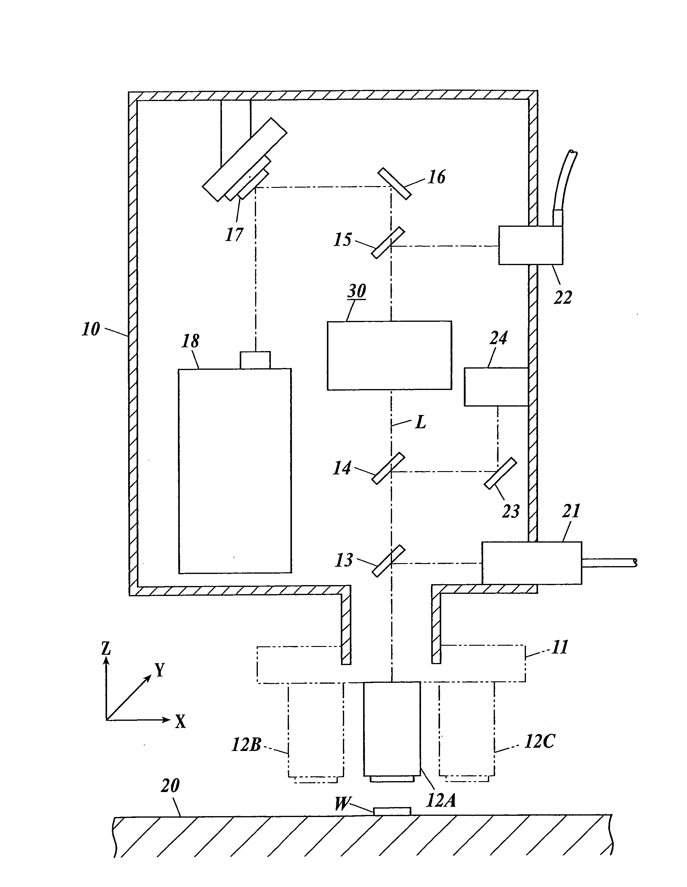
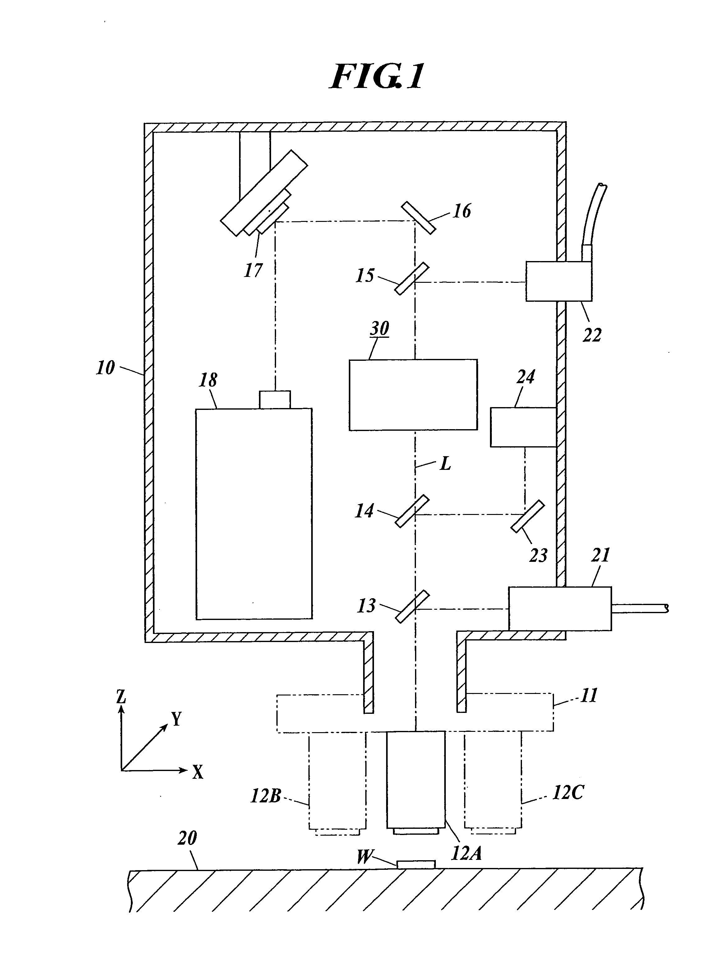
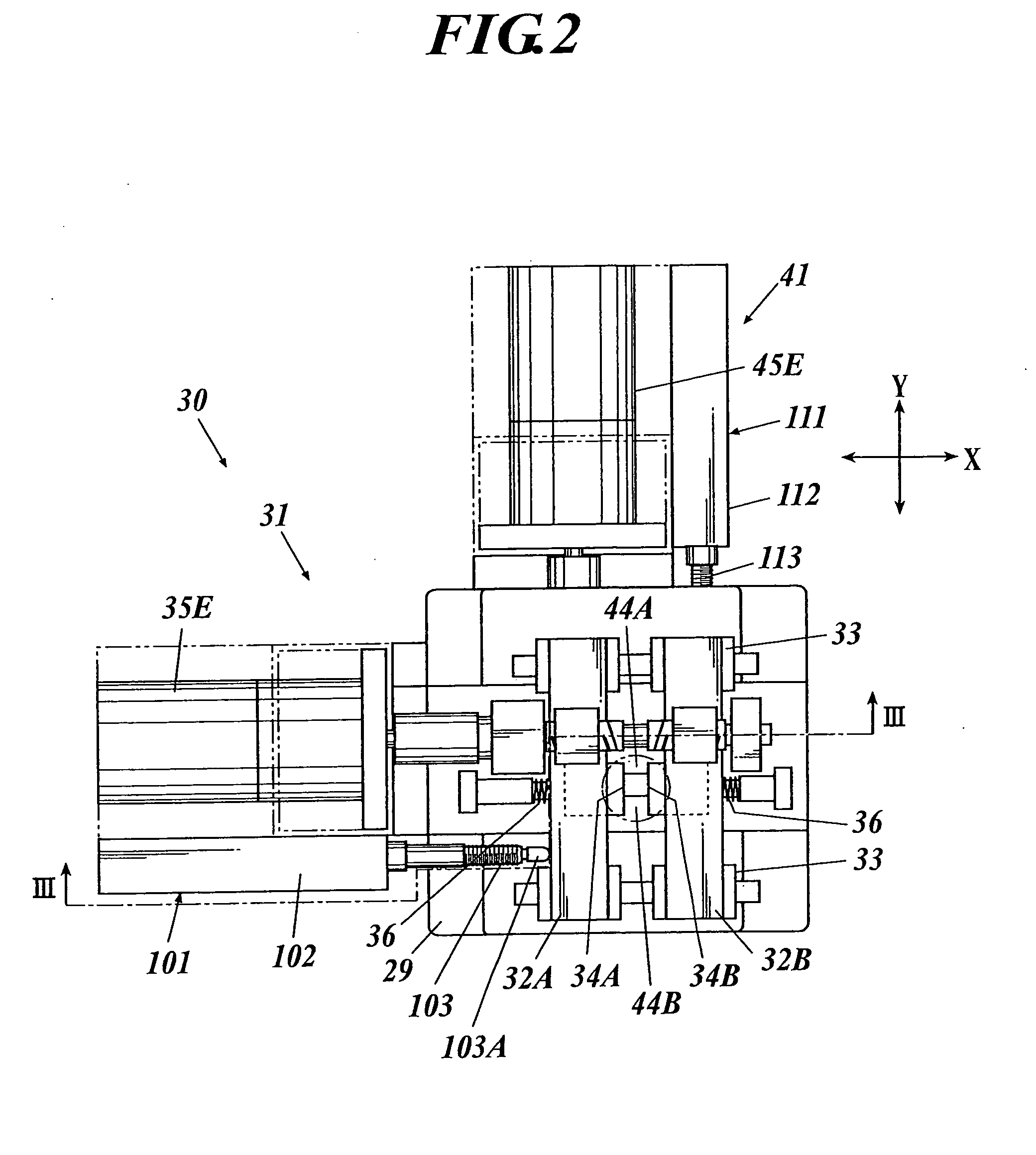
[0025]FIG. 1 is a cross-sectional view showing a microscope laser repair apparatus 1 (the microscope laser processing apparatus) to which a slit width adjusting device 30 according to the present invention is applied; FIG. 2 is a plane view showing the slit width adjusting device 30; FIG. 3 is a cross-sectional view of III-III line of FIG. 2; FIG. 4 is a perspective view showing a first group width adjusting mechanism 31 and an ABS original point sensor 101; FIG. 5 is a perspective view showing a second group width adjusting mechanism 41 and an ABS original point sensor 111; FIG. 6 is a block diagram of the slit width adjusting device 30; and FIG. 7 is a view showing a relationship between a drive instru...


PUM

PropertyMeasurementUnit
Widthaaaaaaaaaa

Abstract

Disclosed is a slit width adjusting device comprising: a pair of slit members parallel to each other, which is moved to approach each other or to be separated from each other to adjust a slit width; a driving section to move the pair of slit members; an absolute position original point detection section to detect an arbitrary absolute position of the slit members as an original point; and an adjustment section to adjust the slit width, wherein the adjustment section comprises: a storage unit to store a slit width table in which a displacement amount of the slit width from the original point, and a drive instruction value corresponding to the displacement amount, are corresponding to each other; and a drive control unit to extract the drive instruction value corresponding to a specified slit width, to drive the driving section according to the extracted drive instruction value.

Description

BACKGROUND OF THE INVENTION[0001]1. Field of the Invention[0002]The present invention relates to a slit width adjusting device and a microscope laser processing apparatus.[0003]2. Description of Related Art[0004]Conventionally, a slit width adjusting device is provided in a laser processing apparatus, and the like, to perform a correction such as a photomask, a flat panel display (FPD), and the like, by laser processing. The slit width adjusting device comprises a variable slit in a light path of a laser light, which is driven by a motor, and the width of the variable slit in the XY direction is adjusted so that the range for which one would like to perform a laser cut matches the slit shape. Thereby, when the laser light is emitted, the laser cut can be performed only for the range which matches the slit shape.[0005]As such a slit width adjusting device, a technique is known in which slit members are in contact, and an original point signal generation electrode which generates an o...

Claims


Application Information

Patent Timeline
IPC IPC(8): B23K26/00G01J1/20G02B26/02
CPCB23K26/0656G03F1/0092G01J1/0448B23K26/032B23K26/067G01J1/0462B23K26/04G02B5/005B23K26/066G03F1/72B23K26/08B23K26/70G01J3/04G02B26/02
Inventor ASANO, HIDEMITSUUWADA, MAKOTOKAIEDA, MAKOTO
Owner MITUTOYO CORP
Learn More