
Thermoelectric conversion material and method of producing the same

a technology thermal conversion material, which is applied in the direction of thermoelectric device junction material, thermoelectric device manufacture/treatment, electrical apparatus, etc., can solve the problems of difficult to improve the performance of thermoelectric conversion material, and prior art is not closely studying a state. achieve the effect of reliable suppression of insulating material

Inactive Publication Date: 2009-12-24
TOYOTA JIDOSHA KK
View PDF3 Cites 29 Cited by
  • Summary
  • Abstract
  • Description
  • Claims
  • Application Information

AI Technical Summary

Benefits of technology

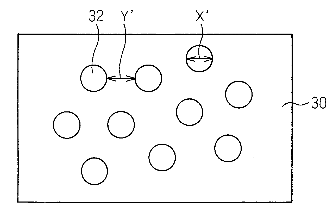
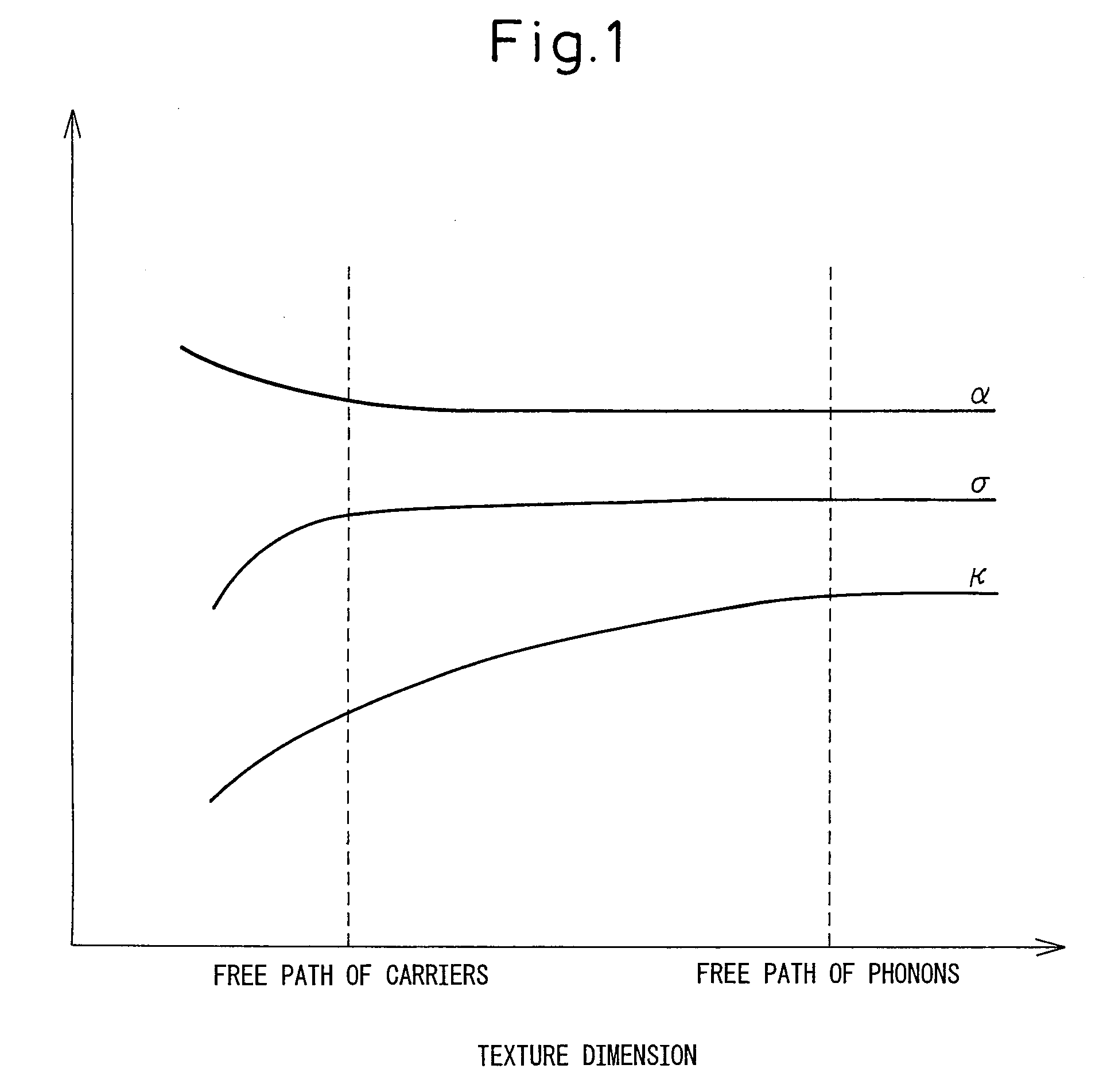
[0014]According to the above invention <1>, the gap of dispersion of at least part of the insulating materials is rendered to be not larger than the mean free path of the phonons in the thermoelectric conversion material, so that the phonons are scattered to a sufficient degree causing a decrease in the thermal conductivity κ of the thermoelectric conversion material and that the electric resistivity and like are suppressed from being deteriorated by the uneven distribution of the insulating material enabling the figure of merit ZT to be further improved.<2> The thermoelectric conversion material of <1> above, wherein at least part of the insulating material has a particle size not larger than the mean free path of the phonons in the thermoelectric conversion material.<3> The thermoelectric conversion material of <1> or <2> above, wherein at least part of the insulating material is dispersed maintaining a gap not smaller than a mean free path of the carriers in the thermoelectric conversion material but not larger than the mean free path of the phonons in the thermoelectric conversion material.
[0017]Besides, it is made possible to suppress the deterioration in the electric resistivity caused by uneven distribution of the insulating material and, therefore, to further increase the figure of merit ZT.<4> A thermoelectric conversion material of the P-type or N-type in which an insulating material is dispersed, wherein at least part of the insulating material has a particle size not larger than a mean free path of the phonons in the insulating material.
[0018]The above invention <4> makes it possible to decrease the thermal conductivity κ of the thermoelectric conversion material and, therefore, to increase the figure of merit ZT. The thermal conductivity decreases if the phonons are scattered to a sufficient degree in the thermoelectric conversion material. Through the step of arriving at the present invention, the inventors have clarified that the phonons are scattered to a sufficient degree when the insulating material dispersed in the thermoelectric conversion material has a particle size not larger than the mean free path of the phonons in the insulating material. This effect is exhibited when at least part of the insulating material that is contained in the thermoelectric conversion material has a particle size not larger than the mean free path of the phonons.
[0023]According to the invention <8> above, the thermoelectric conversion material can be produced by uniformalizing the gap of dispersion of the insulating material and suppressing a decrease in the electric resistivity caused by uneven distribution of the insulating material.
[0025]According to the present invention, on the other hand, the surfaces of the particles constituted by an insulating material are coated with a thermoelectric conversion material to form composite nano particles of which the core portions are constituted by the insulating material and the shell portions are constituted by the thermoelectric conversion material. Upon packing and sintering the composite nano particles, the shell portions (coating layers formed of the thermoelectric conversion material) of the neighboring composite nano particles are bonded together. Therefore, the gap of dispersion of the insulating material can be controlled relying upon the thickness of the shell portions, i.e., the insulating material becomes less likely to be bonded together making it possible to reliably suppress the insulating material from being unevenly distributed.

Problems solved by technology

However, in a conventional thermoelectric conversion materials, inert fine particles are unevenly distributed so that the electric resistivity and other properties are more deteriorated than the effect of scattering the phonons by the inert fine particles, making it difficult to improve performance of the thermoelectric conversion material.
Besides, the prior art is not closely studying a state where the inert fine particles are dispersed.

Method used


Image

  • Thermoelectric conversion material and method of producing the same
  • Thermoelectric conversion material and method of producing the same
  • Thermoelectric conversion material and method of producing the same

Examples


examples

[0079]A slurry (1) was prepared by dispersing 3.6 g of NaBH4 and 12 g of alumina (mean particle size of 15 to 25 nm) in 100 mL of ethanol. Further, a slurry (2) was prepared by adding 1.00 g of CoCl2.6H2O and 2.88 g of SbCl3 to 100 mL of ethanol and further adding thereto the nitric acid as a pH-adjusting agent to adjust the pH thereof to be 6.0.

[0080]The above slurry (1) was added dropwise to the slurry (2), and the mixture was held at 25° C. for 0.5 hours, so that nano particles of Co and Sb were precipitated on the alumina particles. The slurry was filtered and the filtrate was introduced into a mixed solution of ethanol, and water, which was thereafter, stirred and filtered. This operation was repeated twice. After filtered two times, ethanol was added thereto to prepare 100 mL of slurry.

[0081]The obtained slurry was heat-treated in an autoclave container at 240° C. for 24 hours to obtain composite nano particles.

[0082]By using an electric discharge plasma sintering apparatus (S...


PUM


Abstract

A thermoelectric conversion material wherein at least a part of the insulating material contained in the thermoelectric conversion material has a particle size not larger than a mean free path of the phonons in the insulating material or wherein a dispersion gap of the insulating material is not larger than a mean free path of the phonons in the thermoelectric conversion material, and a method of producing the thermoelectric conversion material comprising the steps of forming composite nano particles by reducing and precipitating starting particles of a thermoelectric conversion material on the nano particles constituted by an insulating material, followed by a heat treatment to coat the nano particles with the thermoelectric conversion material; and packing and sintering the composite nano particles.

Description

TECHNICAL FIELD[0001]This invention relates to a thermoelectric conversion material and to a method of producing the same. More specifically, this invention relates to a thermoelectric conversion material which contains an insulating material and to a method of producing the same.BACKGROUND ART[0002]The figure of merit ZT of a thermoelectric conversion material that utilizes a Seebeck effect can be expressed by the following formula (1),ZT=α2σT / κ  Formula (1)[0003]where α, σ, κ and T are a Seebeck coefficient, an[0004]electric conductivity, a thermal conductivity and a measured temperature, respectively.[0005]To improve performance of the thermoelectric conversion material as will be obvious from the formula (1), it is important to increase the Seebeck coefficient α and the electric conductivity σ of the material that is used and to decrease the thermal conductivity κ.[0006]To decrease the thermal conductivity κ of a material, fine particles (inert fine particles) that do not react ...

Claims


Application Information

Patent Timeline
IPC IPC(8): H01L35/34H01L35/12
CPCH01L35/34H01L35/18H10N10/853H10N10/01
Inventor MURAI, JUNYAKITA, TAKUJI
Owner TOYOTA JIDOSHA KK
Learn More