
Solar absorptive coating system

a coating system and solar energy technology, applied in the direction of electrophoretic coatings, coatings, lighting and heating apparatus, etc., can solve the problems of poor absorption/emission ratio of 1.09, and achieve the effects of improving heat conduction through the coating, improving sunlight absorption, and reducing the re-emission of heat energy

Inactive Publication Date: 2009-12-24
WISYS TECH FOUND
View PDF5 Cites 15 Cited by
  • Summary
  • Abstract
  • Description
  • Claims
  • Application Information

AI Technical Summary

Benefits of technology

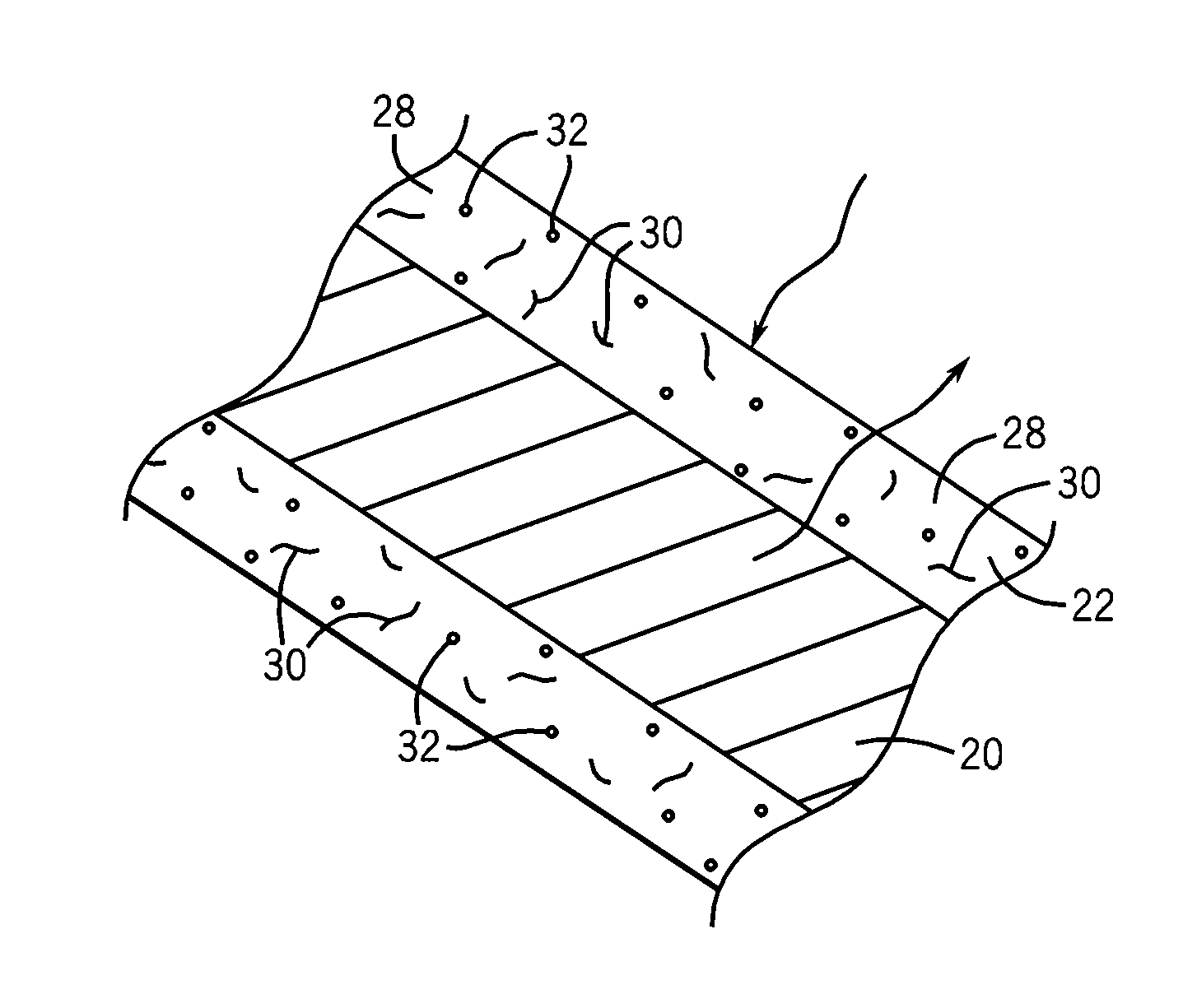
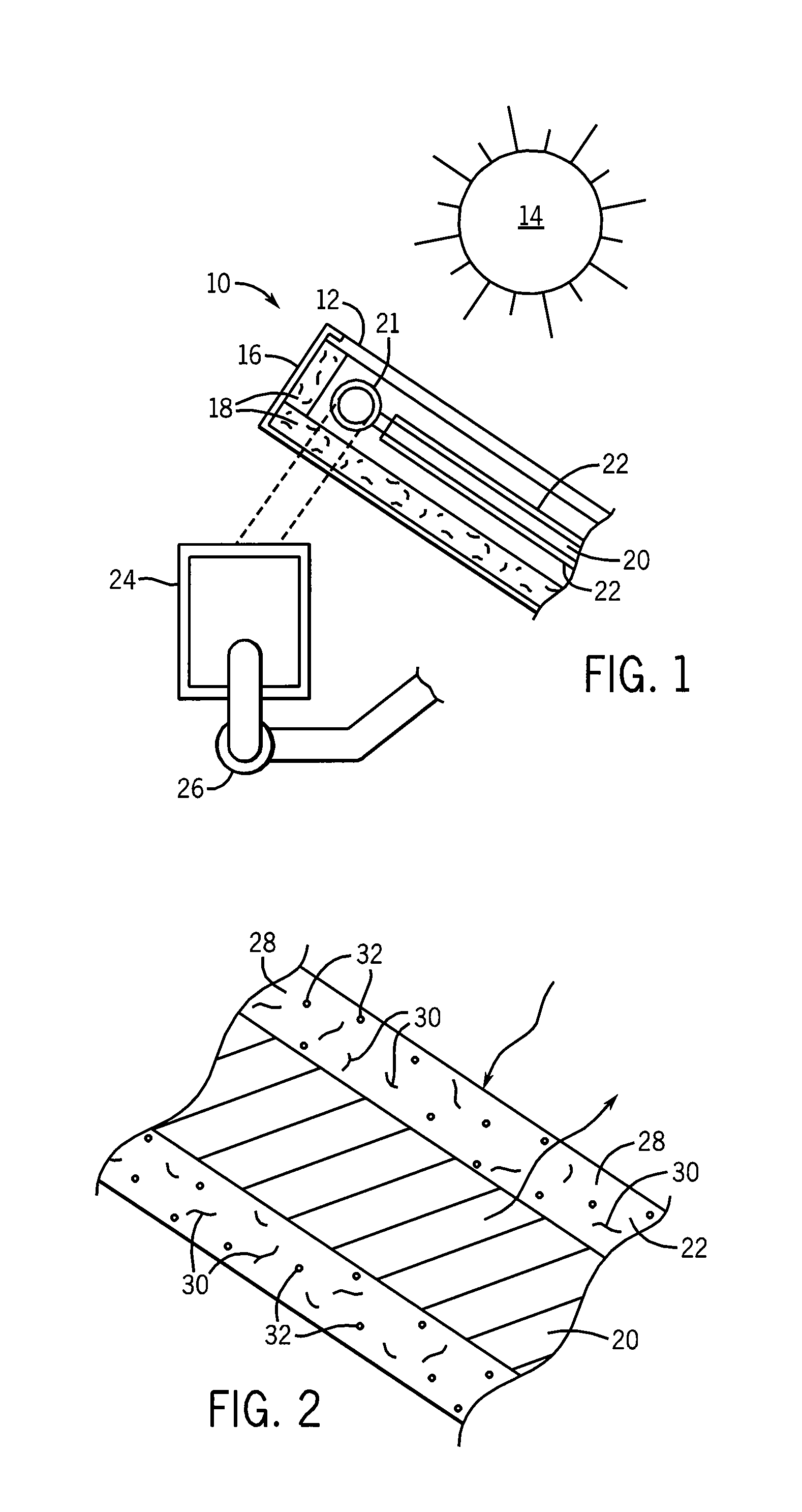
[0011]While the inventor does not wish to be bound by a particular theory, it is believed that the carbon nanotubes improve the absorption of sunlight in the UV, visible and infrared, regions based on their physical structure and provide improved heat conduction through the coating to the underlying metallic substrate. It is probable that the carbon nanotubes contribute significantly to the strength of the matrix of aluminum oxide.
[0012]The nano particulate aluminum oxide provides a binder and separator for the carbon nanotubes and carbon black. The optical properties of aluminum oxide are appropriate for allowing transmission of solar radiation therethrough and because the resulting coating has been demonstrated to be about 50% porous, the coating should act as a thermal insulator to reduce the re-emission of heat energy from the collector substrate.

Problems solved by technology

In comparison, common carbon black paint offers excellent absorption characteristics, 0.96, but demonstrates poor emission characteristics, 0.88, leading to an absorption / emission ratio of 1.09.

Method used


Image

  • Solar absorptive coating system
  • Solar absorptive coating system

Examples


example i

[0019]Nano particulate aluminum oxide was prepared using the alcohol process described, for example, in “The Effects of Surface Adsorption and Confinement on the Photochemical Selectivity of Previtamin D3 Adsorbed Within Porous Sol-Gel Derived Alumina”, Schultz, F. S., Anderson, M. A., Journal of the American Chemical Society, 1999, 121, 4933-4940, hereby incorporated by reference. The resulting nano particulate aluminum oxide had the following characteristics: 6-10 nm in diameter γ-Al2O3 particles with an overall porosity of ˜50%. Generally, the term nanoscale will mean particles less than 1000 nm in diameter and the aluminum oxide particles are preferably less than 100 nm in diameter.

[0020]Carbon nanotubes and carbon black obtained from Cheap Tubes, Inc. of Brattleboro, Vt. and comprising approximately 90% percent single-walled carbon nanotubes and these characteristics, an outer diameter of 1-2 nm and a length of 5-30 um (and preferably less than 100 μm) were then suspended in aq...

example ii

[0022]Sol-gel derived nano-particulate alumina oxide was obtained through hydrolysis of aluminum tri-sec-butoxide. The resulting sol was diluted to 50% and CNTs and polyvinylpyrrolidone (PVP) was added with sonication to create a solution / suspension of CNTs and alumina particles in water.

[0023]Deposition of the coating was accomplished through electrophorectic deposition. The aluminum panel to be coated was the cathode (negative) and a copper plate is used for the anode (positive) with the plating voltage kept constant at 5 volts while the current and plating time controlled by the spacing between the anode and cathode. Ethanol was added to the solutions to reduce hydrogen gas formation at the cathode.

[0024]Using the electrophoretic process only the side of the aluminum substrate facing the anode was coated with the alumina / CNT coating. This raises the possibility of coding only one side of the formal collector or changing the formulation of the coating material (for example to remo...


PUM

PropertyMeasurementUnit
diameteraaaaaaaaaa
lengthaaaaaaaaaa
porosityaaaaaaaaaa

Abstract

A paintable, low VOC coating improving the solar absorption of materials consists of an aqueous suspension of nanoparticle aluminum oxide, carbon nanotubes, and carbon black.

Description

CROSS REFERENCE TO RELATED APPLICATIONS[0001]This Application claims the benefit of U.S. Provisional Application 61 / 075,235 filed Jun. 24, 2008 and hereby incorporated by reference.BACKGROUND OF THE INVENTION[0002]Heat and hot water costs represent the largest portion of a typical monthly utility bill for both homes and businesses. Solar hot water heating is a promising technology for harnessing the energy of the sun to replace up to 75% of the fossil fuels consumed in these applications.[0003]A typical solar heating system requires a solar collector having high absorption in the spectral range of the sun and low emissivity (re-radiation of energy from the collector). Good thermal conductivity in the collector is required to transfer the absorbed heat, typically to circulating water, for storage and later use in air and water heating.[0004]The combination of qualities needed for a solar collector are often obtained through the use of a metallic collector plate (aluminum or copper) c...

Claims


Application Information

Patent Timeline
Patent Type & Authority Applications(United States)
IPC IPC(8): F24J2/46B23P25/00
CPCB82Y30/00Y10T29/49885C04B35/63444C04B35/803C04B2235/322C04B2235/424C04B2235/526C04B2235/5264C04B2235/5288C04B2235/5454C25D13/02F24J2/26F24J2/485H01L31/02167H01L31/048Y02E10/44Y02E10/50C04B35/117F24S10/75F24S70/225C04B35/80
Inventor SCHULTZ, FORREST S.
Owner WISYS TECH FOUND
Learn More