Printing head
- Summary
- Abstract
- Description
- Claims
- Application Information
AI Technical Summary
Benefits of technology
Problems solved by technology
Method used
Image
Examples
first embodiment
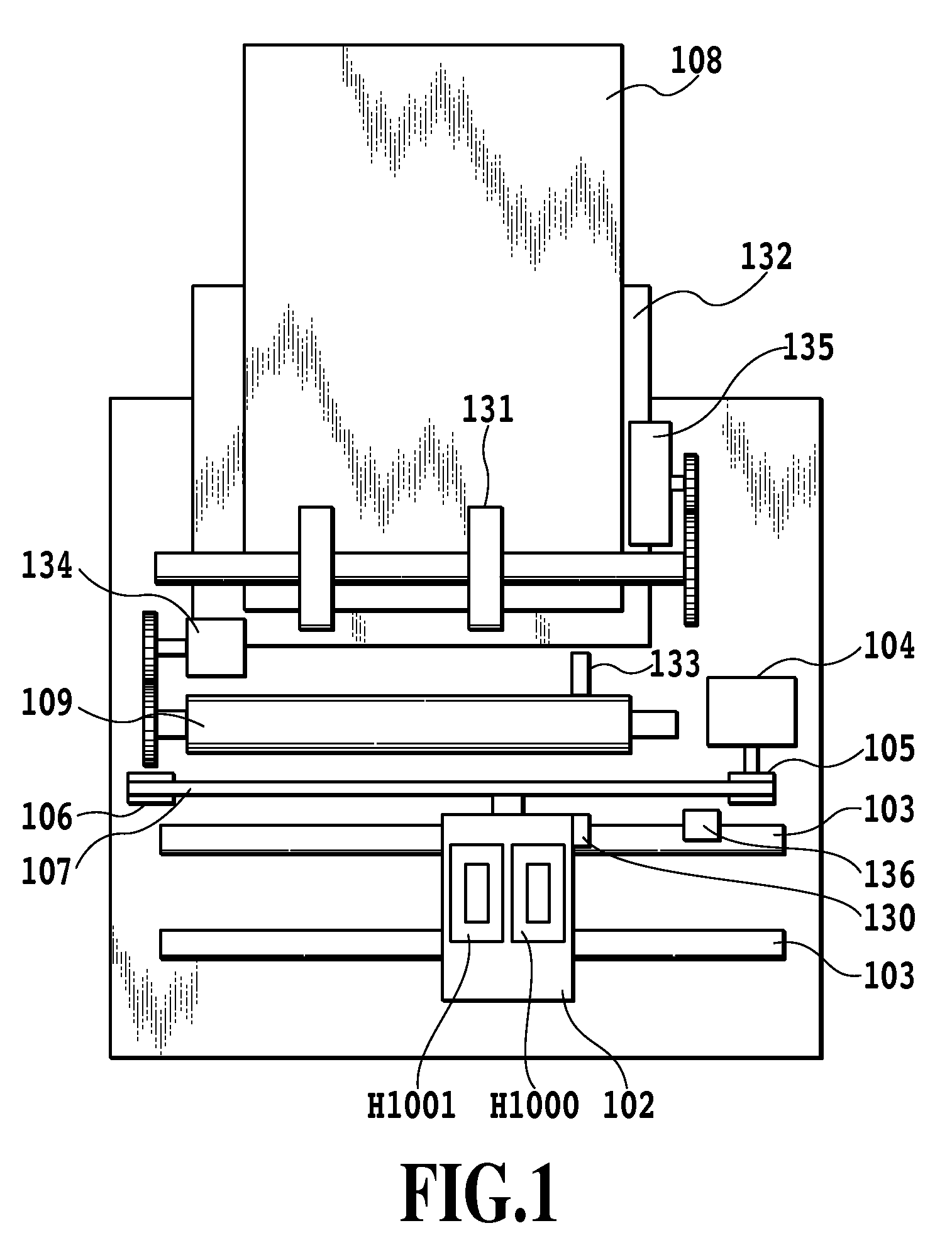
[0037]FIG. 1 is a schematic structural view showing a configuration of an inkjet printing apparatus in an embodiment of the present invention. The inkjet printing apparatus repeats an operation of reciprocating a first printing head H1000 and a second printing head H1001 in a main-scanning direction and an operation of conveying a printing medium 108 in a sub-scanning direction at every predetermined pitch. In synchronization with these movements, ink is selectively ejected from the first printing head H1000 and the second printing head H1001 and applied to the printing medium 108, thereby forming texts, symbols, images, and the like.
[0038]The first printing head H1000 and the second printing head H1001 are detachably mounted on a carriage 102. The carriage 102 is slidably supported by a guide shaft 103, and is reciprocated along the guide shaft 103 by a driving means of a non-illustrated motor or the like. The printing medium 108 faces toward ink ejection surfaces of the first prin...
second embodiment
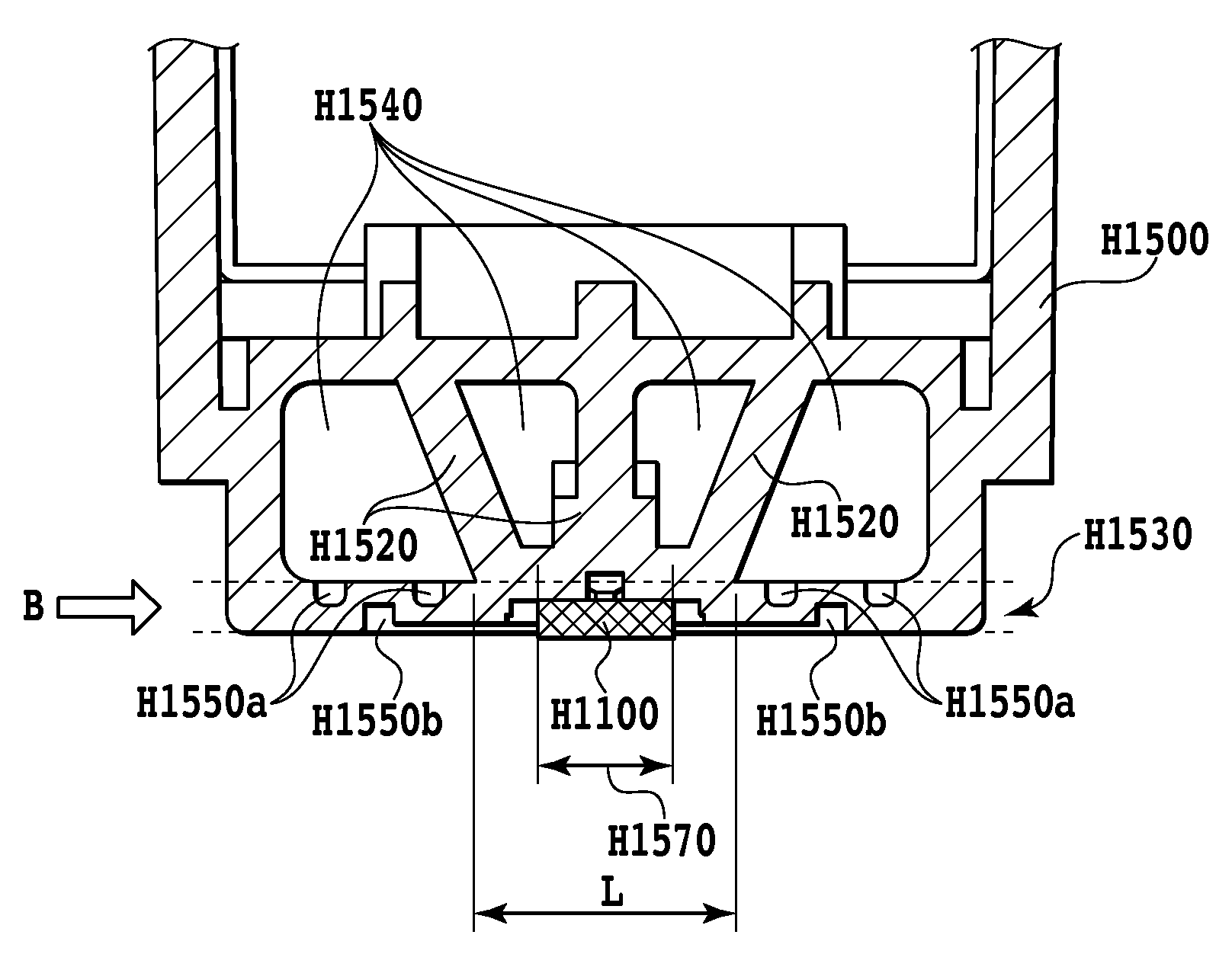
[0059]In the printing head of the first embodiment, the groove H1550a is formed as the concave portion in the rear surface of the region between the printing element substrate and the corner portion R of the major surface of the sheet-shaped portion, of the sheet-shaped portion. However, the present invention is not limited to the concave portion. A structure for absorbing an impact may be formed in the region between the printing element substrate and the corner portion R of the major surface of the sheet-shaped portion, of the sheet-shaped portion holding the printing element substrate.
[0060]FIG. 10 and FIG. 11 are views showing a structure of the first printing head of this embodiment.
[0061]FIG. 10 is an outline view showing only an ink container H1502 and the printing element substrate H1100 among the components constituting the first printing head H1000. A mounting guide H1562 plays a role as a guide for guiding the first printing head H1000 to the mounting position of the carr...
modification embodiment
of the Second Embodiment
[0064]FIG. 12 and FIG. 13 are views showing a structure of the first printing head of an alternative embodiment of the second embodiment.
[0065]FIG. 12 is an outline view showing only an ink container H1503 and the printing element substrate H1100 among the components constituting the first printing head H1000. A mounting guide H1563 plays a role as a guide for guiding the first printing head H1000 to the mounting position of the carriage 102 of the main body of the inkjet printing apparatus.
[0066]FIG. 13 is a cross-sectional view showing a cross section along a XIII-XIII line in FIG. 12. The printing element substrate H1100 is bonded to a bonding region H1573 by adhesive. A cavity portion H1543 is provided for improving the molding stability of the ink container H1500 formed by resin-molding. Then, in a sheet-shaped portion holding the printing element substrate, there is formed a vertical hole H1553 that is a through-hole extending through the major surface ...
PUM
 Abstract
Description
Claims
Application Information
 - R&D
- Intellectual Property
- Life Sciences
- Materials
- Tech Scout
- Unparalleled Data Quality
- Higher Quality Content
- 60% Fewer Hallucinations
Browse by: Latest US Patents, China's latest patents, Technical Efficacy Thesaurus, Application Domain, Technology Topic, Popular Technical Reports.
© 2025 PatSnap. All rights reserved.Legal|Privacy policy|Modern Slavery Act Transparency Statement|Sitemap|About US| Contact US: help@patsnap.com


