
Method and plant for the production of a casing for a solid-propellant engine, and casing made according to said method

a solid-propellant engine and production method technology, applied in cocoa, sweetmeats, closures, etc., can solve the problems of affecting the production efficiency of the engine, the particular geometry of the casing, and the high implementation cost, and achieve the effect of simple and inexpensive solution

Active Publication Date: 2009-12-10
AVIO
View PDF4 Cites 2 Cited by
  • Summary
  • Abstract
  • Description
  • Claims
  • Application Information

AI Technical Summary

Benefits of technology

[0006]The aim of the present invention is to provide a method for the production of a casing for a solid-propellant engine, which will enable a simple and inexpensive solution to the problems set forth above.

Problems solved by technology

For these reasons, the mode of insulation described involves extremely long times and high costs of implementation, there being necessary three distinct working steps, rendered, on the other hand, even more complex by the particular geometry of the casing.
However accurate the operations of production of the shells or caps may be, these frequently have defects and dimensional instability, randomly distributed porosities, and for this reason induce positioning errors or faults.
Even though the maximum care is then taken in positioning and in the subsequent operation of vulcanizing, between the caps and the core there are frequently present areas in which they are not properly stuck together, which, along with the aforesaid porosities, jeopardize sensibly the efficiency of the insulation and consequently the reliability of the casing.

Method used


Image

  • Method and plant for the production of a casing for a solid-propellant engine, and casing made according to said method
  • Method and plant for the production of a casing for a solid-propellant engine, and casing made according to said method
  • Method and plant for the production of a casing for a solid-propellant engine, and casing made according to said method

Examples


Embodiment Construction

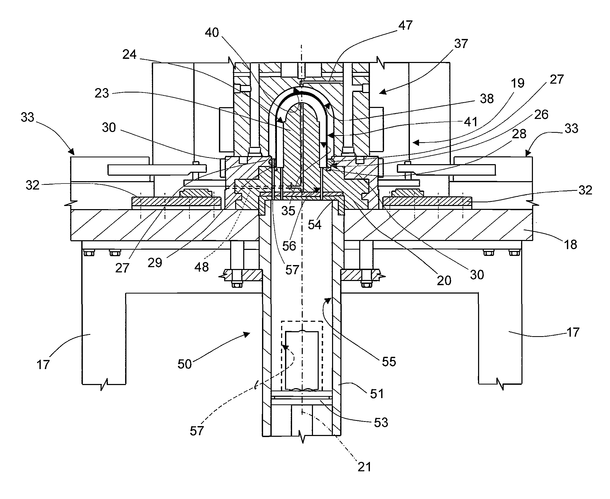
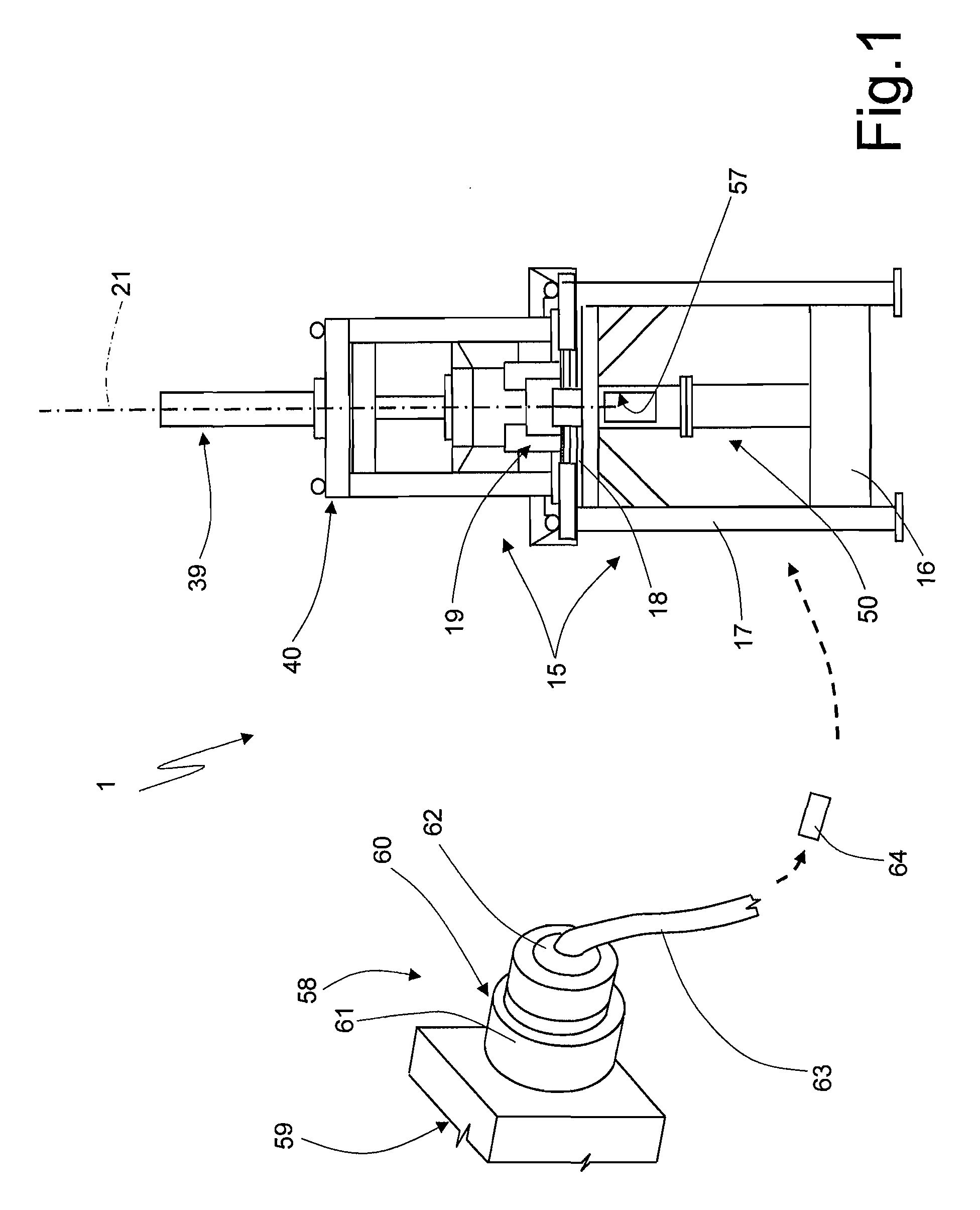
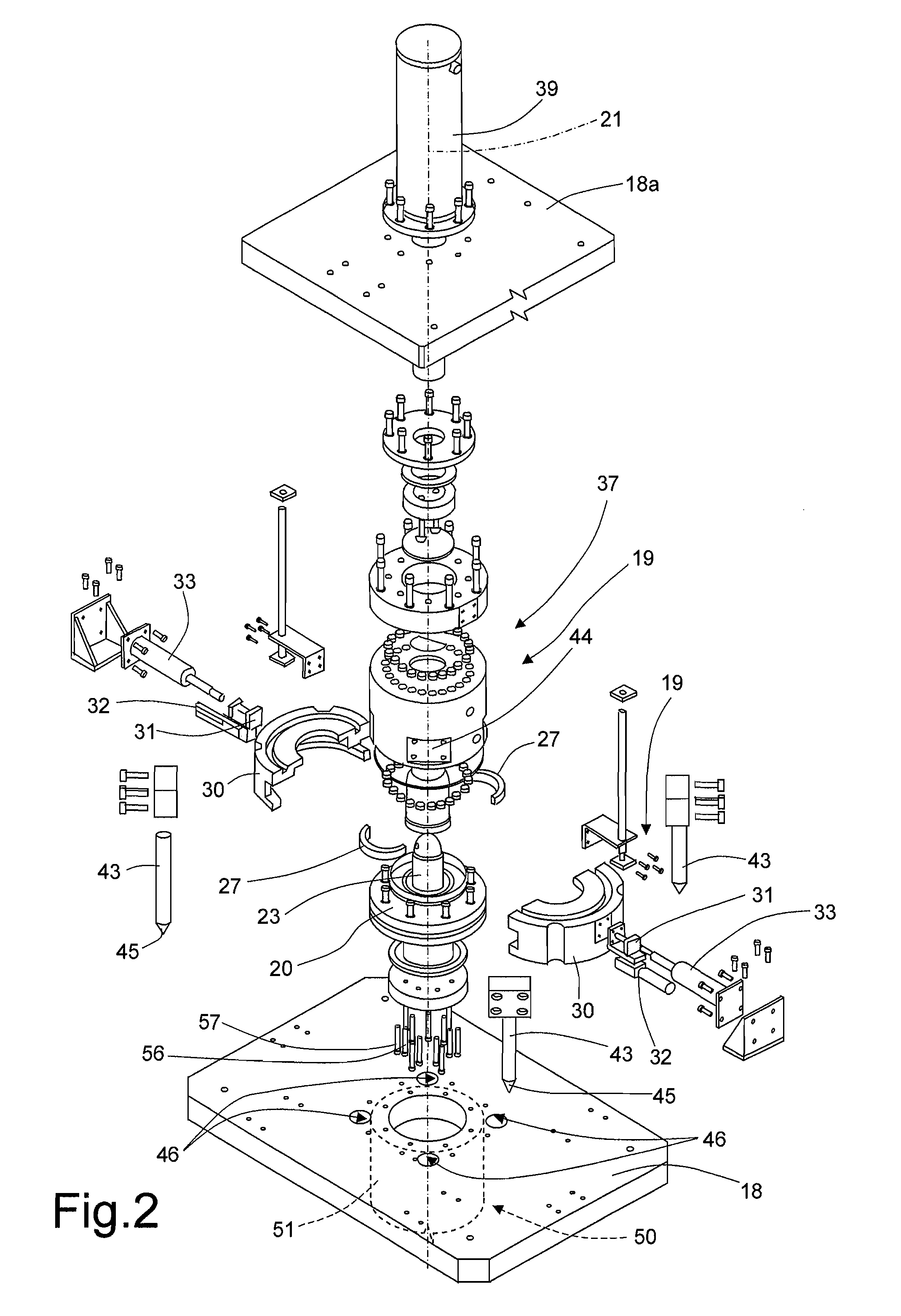
[0024]In FIG. 1, designated as a whole by 1 is a plant for the production of an insulated casing 2 (FIGS. 4 and 5) of a solid-propellant engine (not illustrated) for a rocket engine.

[0025]With reference to FIG. 4, the casing 2 has an axis of symmetry 3 of its own, and comprises a cylindrical tubular intermediate portion 4 coaxial to the axis 3, a spherical-cap portion 5 for closing a longitudinal end of the intermediate portion 4, and an externally threaded cylindrical terminal stretch 6 opposite to the portion 5. The casing 2 is delimited by an inner surface 8 and by an outer surface 9, and is constituted by a core 10, terminating with the stretch 6 and made conveniently of metal material or of other equivalent material resistant to the mechanical and thermal stresses of operation of the casing 2, and by a layer 12 of thermally insulating elastomeric material. The layer 12 coats the core 10 completely except for the part of the terminal stretch 6 provided with the external thread, ...


PUM

PropertyMeasurementUnit
pressureaaaaaaaaaa
massaaaaaaaaaa
distanceaaaaaaaaaa

Abstract

A casing of a solid-propellant engine comprising a core and a layer of elastomeric material, set as coating for at least part of the core to provide a thermal protection of the core itself is obtained by: inserting the core in a forming mould so as to make within the mould two annular chambers separated from one another by the core; forming a strand of elastomeric material; obtaining a defined portion of elastomeric material by cutting the strand transversely to size in an external environment; and injecting the cut portion of elastomeric material simultaneously within both of the annular chambers.

Description

[0001]The present invention relates to a method for producing a casing for a solid-propellant engine for a rocket engine.BACKGROUND OF THE INVENTION[0002]As is known, a solid-propellant engine comprises a casing filled with solid propellant, a device for ignition of the propellant, and a terminal nozzle, through which the propellant, by burning, generates a desired propulsive thrust. The casing comprises a core made of steel or of a composite material, which has a cylindrical tubular portion and a closing portion shaped like a spherical cap and is insulated by being coated both internally and externally with a layer of specific thermally insulating material to define an adequate thermal protection of the core.[0003]Normally, the layer of thermally resistant material is obtained by forming separately from the core two shells or caps, which, once the core has been formed in vacuum conditions, are, one, inserted within the core bringing it into contact with the internal surface of the ...

Claims


Application Information

Patent Timeline
Patent Type & Authority Applications(United States)
IPC IPC(8): B29D23/00B29C45/02B29C45/03
CPCB29C45/02B29C45/1671B29K2021/00Y10T428/1386B29K2019/00F02K9/346F02K9/343
Inventor MAGISTRALE, GIUSEPPE
Owner AVIO
Learn More