
Current source

a current source and output current technology, applied in the direction of electric variable regulation, process and machine control, instruments, etc., can solve the problem that the current source cannot provide a stable output current, and achieve the effect of stable output curren

Inactive Publication Date: 2009-12-10
RAYDIUM SEMICON
View PDF4 Cites 20 Cited by
  • Summary
  • Abstract
  • Description
  • Claims
  • Application Information

AI Technical Summary

Benefits of technology

[0007]The present invention is directed to a current source capable of providing a substantially stable output current when the co

Problems solved by technology

Thus, the current source cannot provide a stable output current when the conditions, such as the processing technique and the environment temperature, are changed.

Method used


Image

  • Current source
  • Current source
  • Current source

Examples


Embodiment Construction

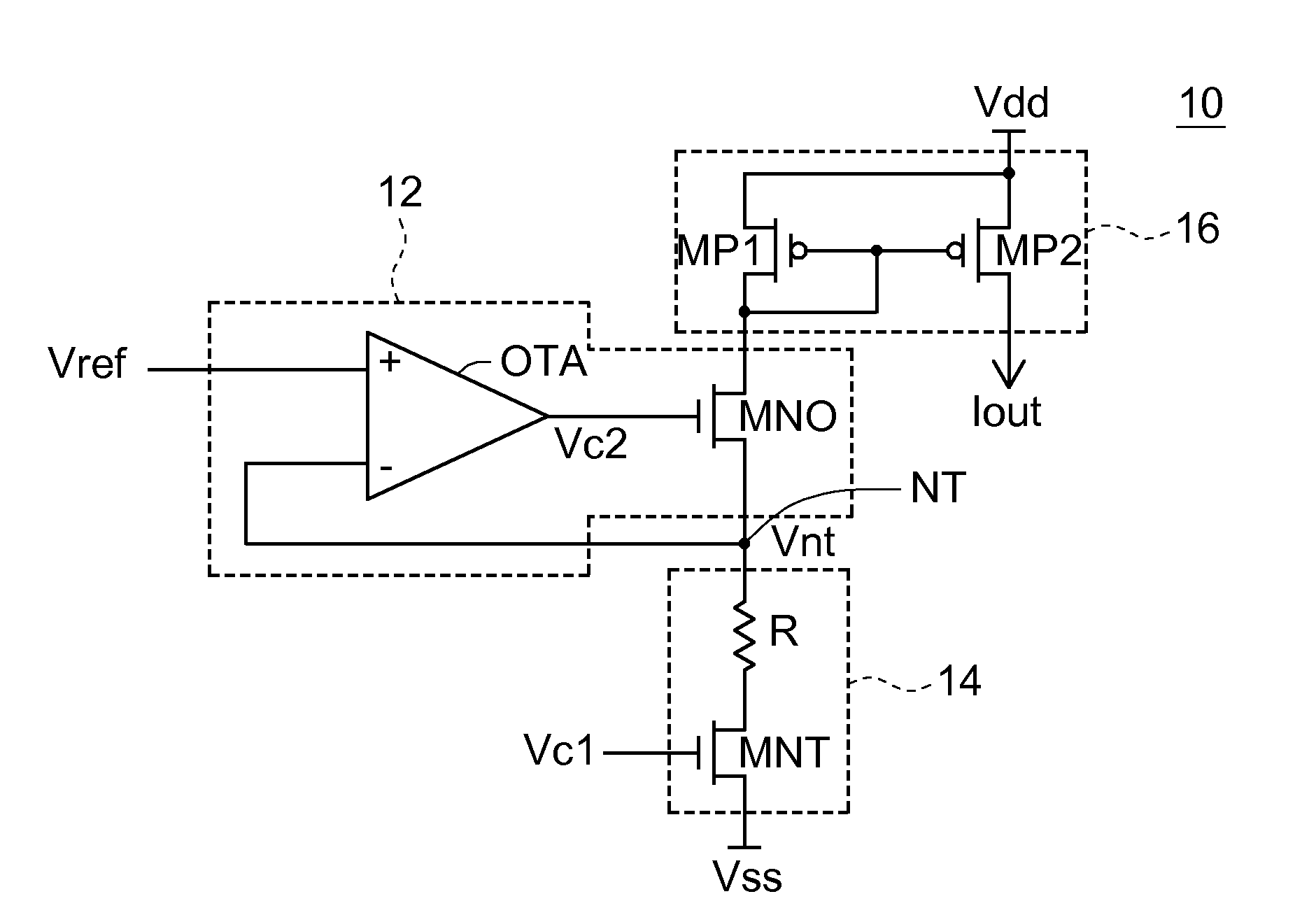
[0016]The current source of this embodiment compensates for the property change of the circuit element, which is caused by the temperature coefficient of the current source and the processing technique, using a serially connected transistor.

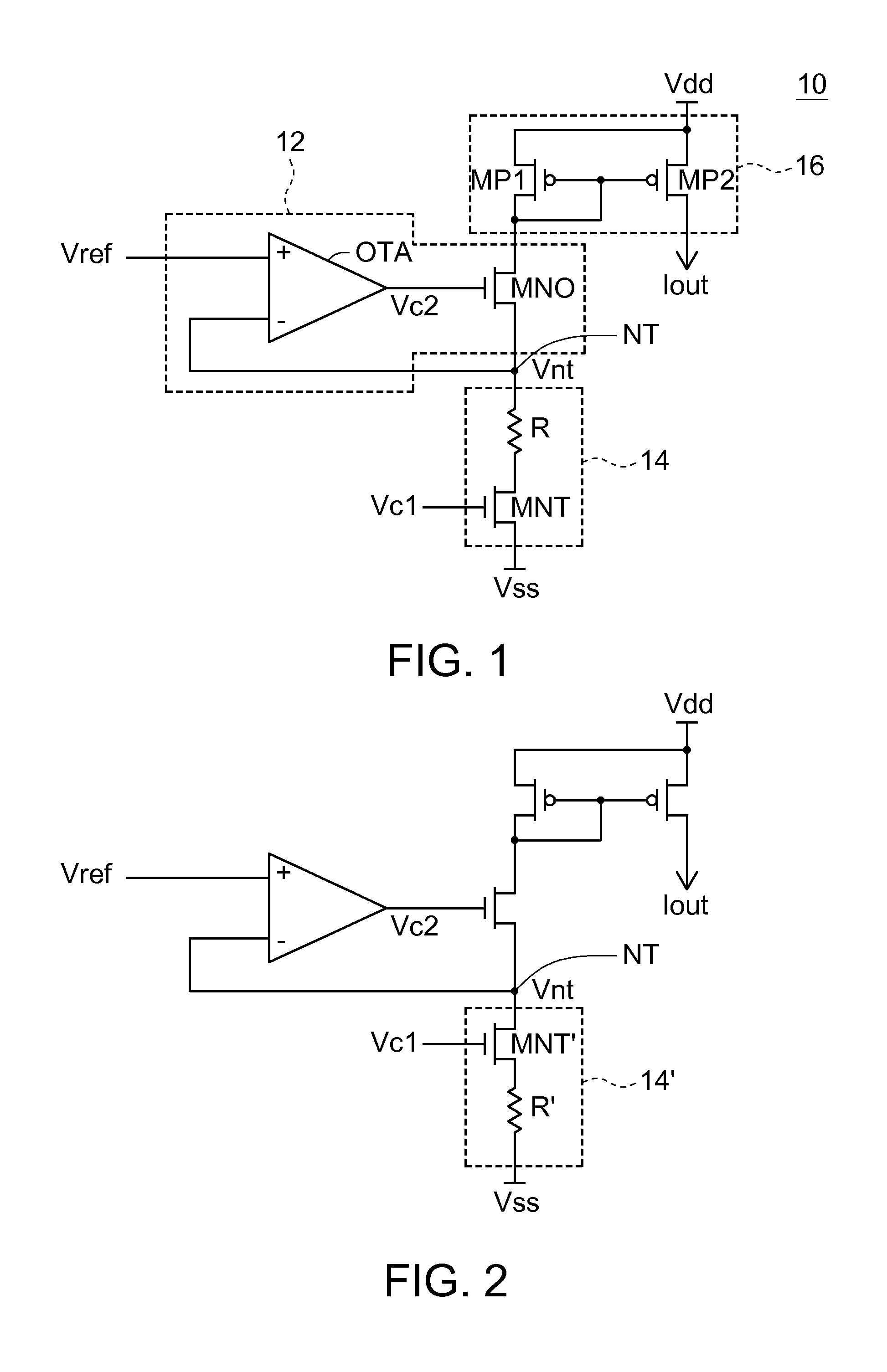
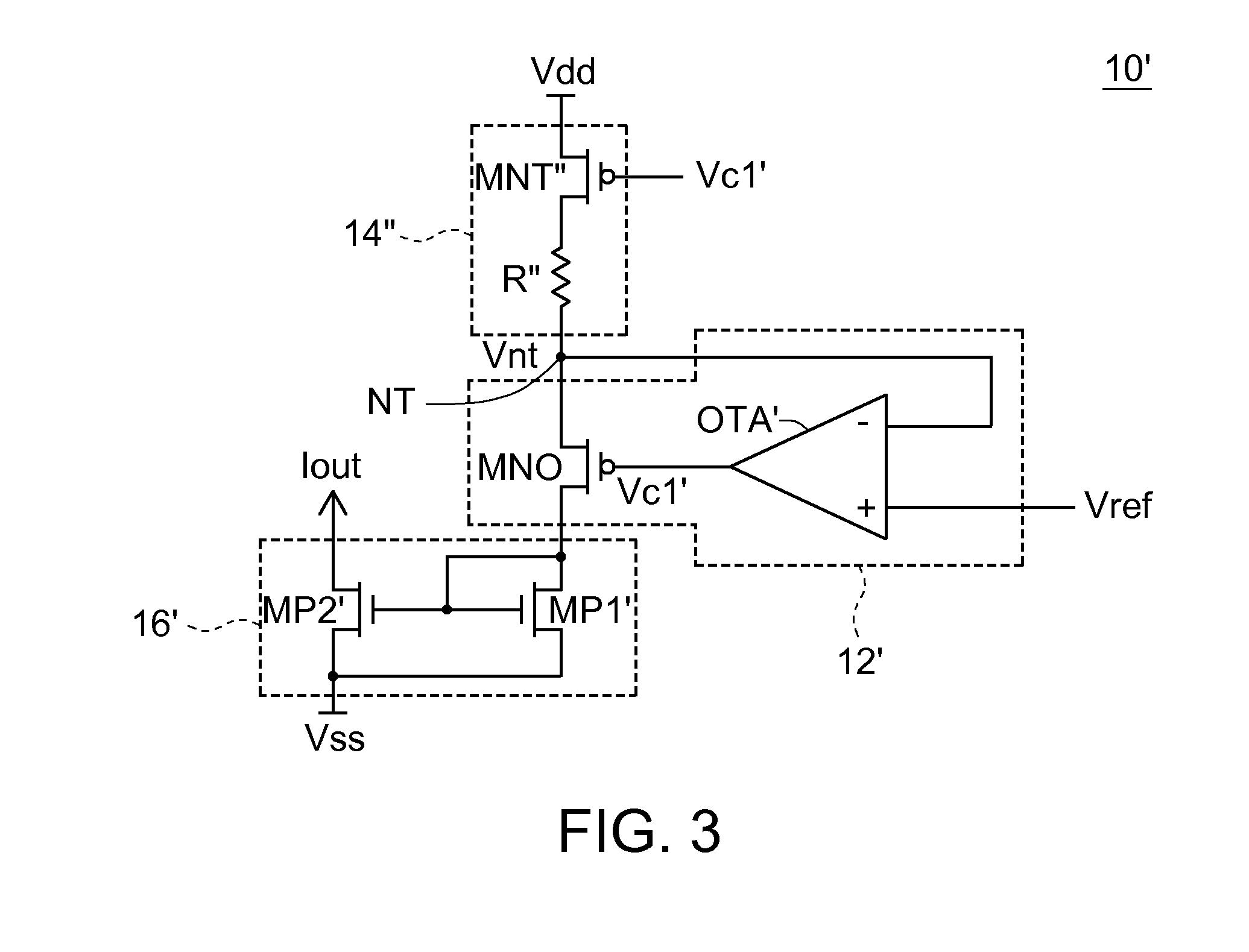
[0017]FIG. 1 is a block diagram showing a current source 10 according to an embodiment of the invention. Referring to FIG. 1, the current source 10 for generating a stable output current Iout includes a node NT, a biasing circuit 12, a loading circuit 14, and a current mirror 16. The node NT has a node voltage Vnt.

[0018]The biasing circuit 12 biases the node voltage Vnt according to a reference voltage Vref so that the node voltage Vnt is biased to be the reference voltage Vref. For example, the biasing circuit 12 includes an operational amplifier OTA and a transistor MNO, such as an N-type metal oxide semiconductor (NMOS) transistor.

[0019]The operational amplifier OTA has a positive input terminal for receiving the reference voltage Vref, a nega...


PUM


Abstract

A current source includes a node, a biasing circuit, a loading circuit and a current mirror. The node has a specified voltage. The biasing circuit biases the specified voltage to be a first reference voltage. The loading circuit provides an equivalent resistor across the node and a second reference voltage to generate a reference current. The loading circuit includes a resistor and a metal oxide semiconductor field effect transistor (MOSFET). The resistor has a first temperature coefficient. The transistor operating in a linear region is controlled by a control voltage to turn on and to form a transistor resistor coupled with the resistor in series. The transistor resistor has a second temperature coefficient, wherein a temperature coefficient of the equivalent resistor is relevant to the first and second temperature coefficients. The current mirror receives the reference current and provides a mirrored current of the reference current as the output current.

Description

CURRENT SOURCE[0001]This application claims the benefit of Taiwan application Serial No. 97120738, filed Jun. 4, 2008, the subject matter of which is incorporated herein by reference.BACKGROUND OF THE INVENTION[0002]1. Field of the Invention[0003]The invention relates in general to a current source, and more particularly to a current source for generating a temperature-independent reference current.[0004]2. Description of the Related Art[0005]In the present technology, a current source has existed and been widely applied to various circuit designs. For example, a transistor is biased by way of current source when an analog circuit is designed. In these applications, the current source is requested to provide a stable output current.[0006]Generally, however, most electrical properties of electrical elements tend to vary with ambient temperature or processing techniques. Similarly, circuit elements applied to the current source also tends to be changed due to the variation of the envi...

Claims


Application Information

Patent Timeline
IPC IPC(8): G05F3/26
CPCG05F3/24
Inventor HSIEH, CHUNG-HSUAN
Owner RAYDIUM SEMICON
Learn More