Solar hybrid agricultural greenroom

Inactive Publication Date: 2009-12-10
TILFORD ARTHUR ROBERT +1
View PDF9 Cites 18 Cited by
  • Summary
  • Abstract
  • Description
  • Claims
  • Application Information

AI Technical Summary

Benefits of technology

[0020]The purpose of this invention is to eliminate as many of the negatives associated with conventional, soil based agricultural as possible while also allowing an unprecedented level of control over the entire growing process.
[0023]Because they were designed for refrigeration, these containers are well insulated and designed for continuous air circulation. They also feature very smooth interiors comprised of either aluminum or stainless thus rendering them efficient reflective surfaces.
[0025]Using tightly sealed containers for agriculture eliminates the effects of weather while also allowing total control of important factors such as temperature, humidity, and airflow. There is no danger of losses from birds or animals and any plant diseases would be limited to just the one container so infected. In this hermetically sealed environment, there is no need for any pesticides to control pests.
[0026]This same sealed environment allows for total control of the water and nutrients that are presented to the growing plants. The water introduced into the growing chambers is carefully filtered and controlled for pH, temperature, and the level of dissolved solids such as sodium, calcium, and magnesium is held to very low levels through the use of reverse osmosis filters.
[0030]Because the refrigerated containers are tightly sealed, it is possible to introduce carbon dioxide into the container to enhance growth rates. The average outdoor levels are now said to be approximately 380 parts per million (PPM) with higher levels in population centers. During those hours when the interior of the chamber is illuminated, plants will grow up to twice as rapidly if the CO2 levels are in the 1,000 to 2,000 PPM range. Infrared meters are used to continuously monitor the levels of CO2 in the container and computerized controls adjust them automatically.
[0031]The present invention accepts specifically filtered and modified light ducted into the growing chamber where it is directed toward the growing plants at the most favorable angles to maximize the growth potential. In this scheme the sunlight is available according to the time of year, however the available light can be concentrated to compensate for lower levels present during the shorter days of the year.

Problems solved by technology

There was no soil on Wake, so hydroponics was employed to grow fruits and vegetables for the passengers because bringing in fresh produce was not economically feasible.
The technology had its problems over the years.
Others, like spikes in energy costs that made heating the greenhouses prohibitively expensive, were not easily solvable.
The downside to this abundance of solar energy is the heat it produces, thus requiring an array of venting and cooling strategies which consume energy to run.
This can be very effective, but there is a high cost in electricity to run these specialized lamps and they also create high levels of ambient heat that must be dealt with at an additional set of costs.
As a direct result, a significant portion of the cost of food is comprised of the costs of transporting it to distant markets.
Moving agricultural products over hundreds and thousands of miles to market expends massive amounts of irreplaceable fossil fuels and also results in the creation of large amounts of greenhouse emissions.
Another difficulty with traditional soil based agriculture is the use of pesticides that help to protect the growing plants from insects.
However, none of the above nor any of the known historic art provides for a teaching where light carrying photons are carefully guided through a hollow specifically shaped hexagonal light waveguide and that incorporate internally-wall-mounted solar cells circumnavigating the waveguide axis in a 360-degree manner with associated internal reflective components positioned in such a manner to allow the complete thru-put of some of the light while utilizing the remaining light in an economical manner where photovoltaic cells absorb such light within the waveguide itself.

Method used


Image

  • Solar hybrid agricultural greenroom
  • Solar hybrid agricultural greenroom
  • Solar hybrid agricultural greenroom

Examples


Embodiment Construction

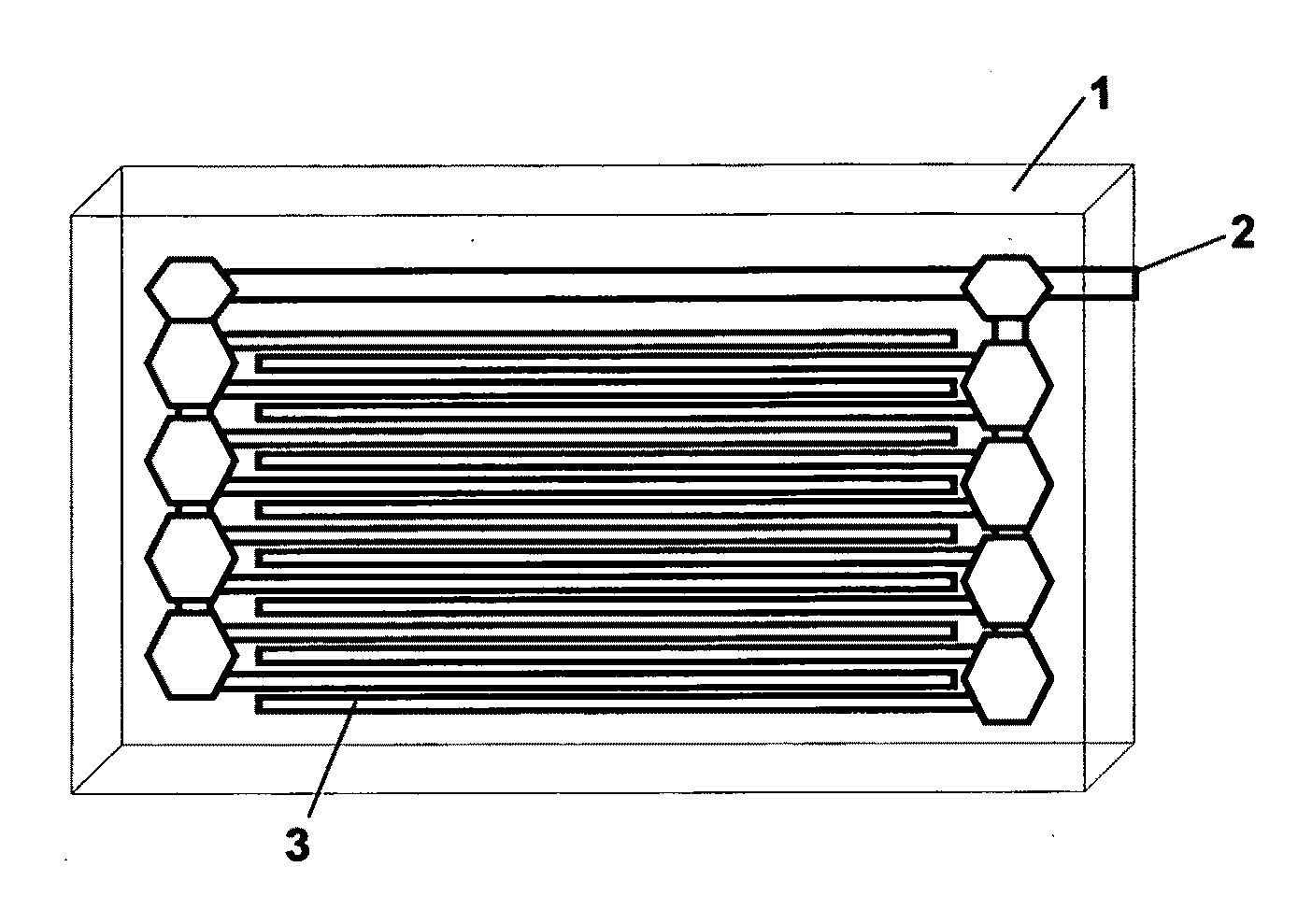
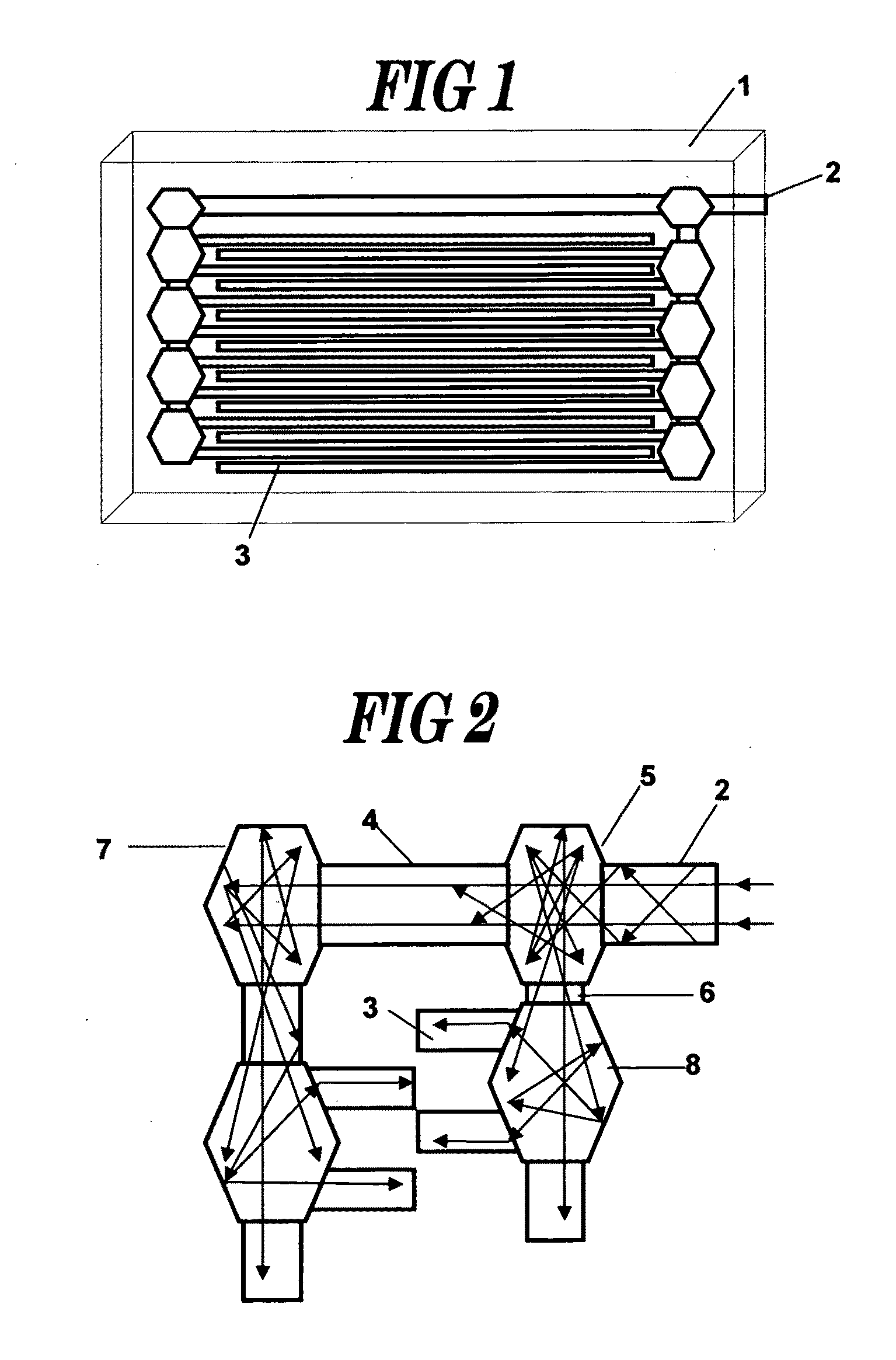
[0043]FIG. 1 illustrates the light emitting array (LEA) 1 with a single light input port 2 which allows the conduction of light directly to the several light emitting conduits 3.

[0044]FIG. 2 illustrates the internal light reflection orientation utilized in the light emitting array (LEA). Filtered and modified light enters the input port 2 and is transmitted through the first internal reflecting unit 5 to the primary non-emitting light conduit 4 where it is re-directed through a second internal reflecting unit 7. Light is also re-directed within the first internal reflecting unit 5 through a vertical non-emitting light conduit 6 to another internal reflecting unit 8 where it is re-directed to one of two light emitting conduits 3. It also passes through the internal reflecting unit 8 to another portion of the light emitting array where the process is repeated until all light emitting conduits are served.

[0045]FIG. 3 illustrates the solar cell array (SCA) 9 which houses an array of sol...


PUM


Abstract

The invention is a methodology and device to accept sunlight that is concentrated, modified and filtered to wavelengths known to promote rapid growth, flowering, and fruiting of plants. Such modified light is introduced into the invented chamber which allows the control of factors such as temperature and humidity, CO2 levels, air circulation, and the circulation of water and nutrients. In its preferred embodiment, the invention will use a portion of the collected light to power an array of photovoltaic (PV) chip arrays with the chamber to provide sufficient electricity to power the fans, pumps, and sensors employed within the growing chamber, making it totally self-sufficient once water, nutrients, and seedlings have been introduced into the system. The system may be used within a solid soil or hydroponics growth system.

Description

PRIOR APPLICATIONS[0001]This application is based on provisional application No. 61 / 131,328 filed Jun. 6, 2008, and claim is made for the benefit of the filing date of the provisional application.FIELD OF THE INVENTION[0002]This invention relates to gathering, concentrating and filtering solar light to enhance, modify, and promote plant growth within a portable, sealed agricultural growing chamber.REFERENCES CITED4,302,069November, 1981Niemi385 / 464,316,048February, 1982Woodall136 / 2534,389,085June, 1983Mori359 / 5914,422,719December, 1983Orcutt385 / 1234,425,907January, 1984Younghouse126 / 6854,460,940July, 1984Mori362 / 5584,471,412September, 1984Mori362 / 5654,765,701August, 1988Cheslak362 / 5604,805,984February, 1989Cobb, Jr.385 / 1334,806,289February, 1989Laursen, et al.264 / 1.294,822,123April, 1989Mori385 / 315,050,946September, 1991Hathaway, et al.385 / 335,054,869October, 1991Doyle385 / 1335,060,119October, 1991Parthasarathy365 / 5655,117,478May, 1992Cobb, Jr., et al.385 / 1335,222,795June, 1993Hed362...

Claims


Application Information

Patent Timeline
IPC IPC(8): A01G9/00A01G31/02A01G9/14
CPCA01G9/1438A01G9/14Y02A40/25Y02P60/12
Inventor TILFORD, ARTHUR ROBERTZIMMERMANN, PHILIP FRANK
Owner TILFORD ARTHUR ROBERT
Why Eureka
Try Eureka