
Controlled deployment handles for bone stabilization devices

Inactive Publication Date: 2009-12-03
SPINEALIGN MEDICAL
View PDF18 Cites 42 Cited by
  • Summary
  • Abstract
  • Description
  • Claims
  • Application Information

AI Technical Summary

Benefits of technology

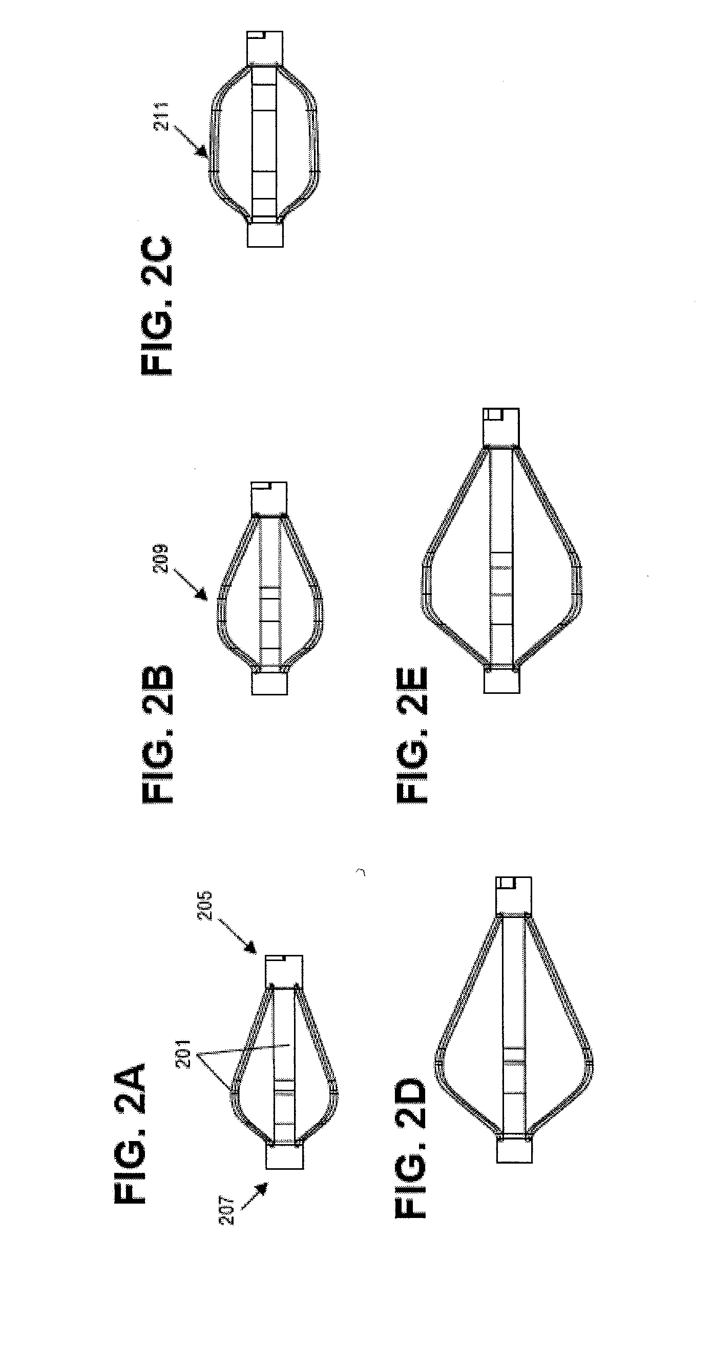
[0017]The implants described herein may also be referred to as bones stabilization devices. These implants may include a self-expanding body that can be deployed in a linear configuration. The deploying configuration is typically an elongate tubular shape that is open at both ends. In some variations the device may have an elongate, substantially tubular shape that includes a plurality of struts extending along the length of the implant in the deployed configuration. For example, the struts maybe extended laterally in an expanded configuration. Expansion of the struts may foreshorten the implant. A self-reshaping (e.g., self-expanding) device may include a preset configuration that is expanded, and may reset from another configuration into the preset configuration (or vice versa). For example, the devices may include a linear configuration (a deployed configuration) and an expanded configuration. The linear configuration can be stabilized by constraints that prevent self-reshaping of the device into an anchoring (expended) configuration. Self-reshaping to an anchoring configuration may be performed by two or more linear portions of the device, which (upon release from constraint) radially-expand into bowed struts of various configurations, while at the same time shortening the overall length of the device. Embodiments of the struts may include a cutting surface on the outwardly leading edge or surface of the strut, which cuts through cancellous bone as it radially expands. After implantation within a vertebral body, the bowed struts may expand though the cancellous bone to contact the cortical bone of the inner surfaces of superior and inferior endplates of the compressed vertebral body, and push the endplates outward to restore the vertebral body to a desired height.
[0029]In general, the expansion and contraction of the implant (and particularly a self-expanding implant) may be controlled. For example, when the implant is converted a (constrained) elongate, tubular delivery configuration having a small cross-section to an expanded configuration in which the struts extend from the body of the device, the implant may be foreshortened. The applicator system controls the deployment of the implant (from the compressed configuration to the expanded configuration) by applying axial force to pull apart (collapse) or draw together (expand) the proximal and distal ends of the implant. One end of the implant (e.g., the distal end) may be held relatively motionless while the applicator system moves the other end to collapse or expand the implant. Preventing the distal end from moving during expansion or collapse may prevent damage to the patient, and may help maintain the position of the implant during insertion. For example, the rotary gear may be configured to axially move the second seat relative to the first seat so that the proximal end of an implant coupled to the first member of the elongate linkage member moves while the distal end of the implant remains relatively stationary.
[0036]The step of rotating the control on the rotary applicator handle may include limiting the axial motion of the first elongate member relative to the second elongate member to prevent damage to the self-expanding implant. A limiter may be included as a stop of other structure within the handle, limiting axial motion to within a specified range. This range may be adjustable in variations of the handle that are used for different sized implants.
[0037]The step of rotating the control on the rotary applicator may comprise moving the first elongate member relative to the second elongate member without substantially moving the second elongate member. As mentioned above, this may prevent movement of the distal end of the implant.

Problems solved by technology

Osteoporosis leads to bone fragility and an increase fracture risk.
While osteoporosis affects the entire skeleton, it commonly causes fractures in the spine and hip.
Spinal or vertebral fractures have serious consequences, with patients suffering from loss of height, deformity, and persistent pain that can significantly impair mobility and quality of life.
Vertebral compression fractures (VCFs) and hip fractures are particularly debilitating and difficult to effectively treat.

Method used


Image

  • Controlled deployment handles for bone stabilization devices
  • Controlled deployment handles for bone stabilization devices
  • Controlled deployment handles for bone stabilization devices

Examples


Embodiment Construction

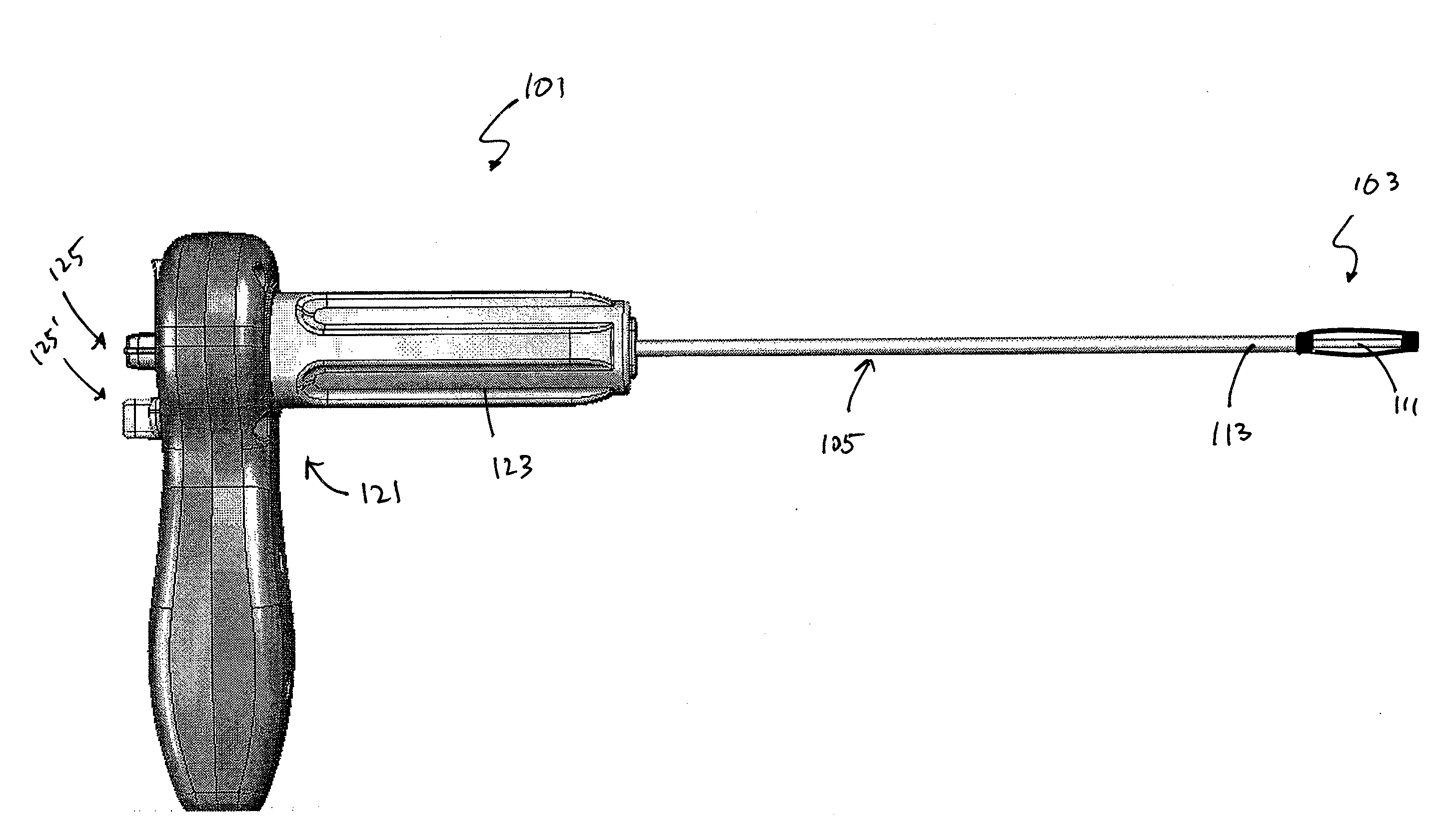
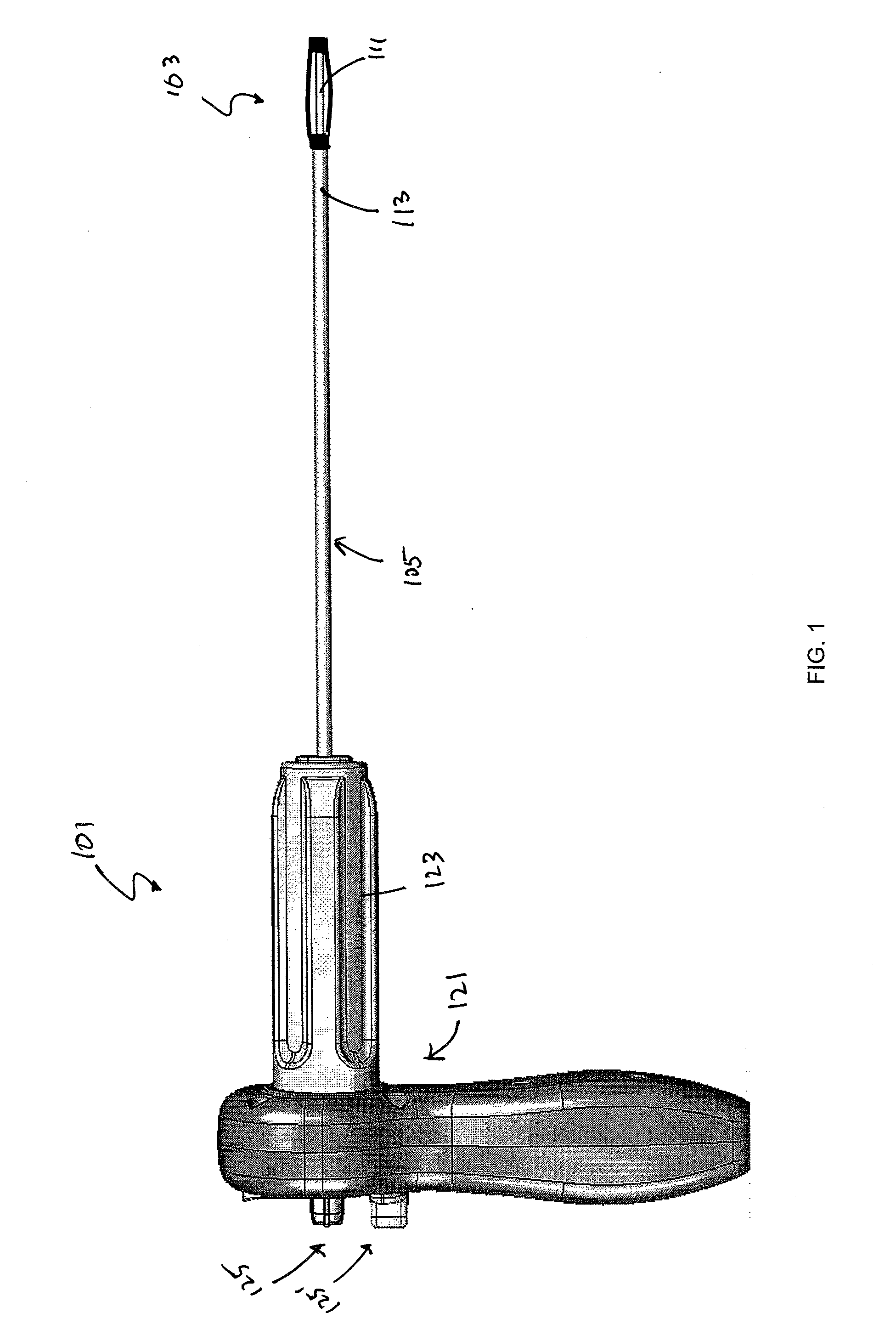
[0079]The devices, systems and methods described herein may aid in the treatment of fractures and microarchitetcture deterioration of bone tissue, including vertebral compression fractures (“VCFs”). The implantable stabilization devices described herein (which may be referred to as “implants,”“stabilization devices,” or simply “devices”) may help restore and / or augment bone. Thus, the stabilization devices described herein may be used to treat pathologies or injuries. For purposes of illustration, many of the devices, systems and methods described herein are shown with reference to the spine. However, these devices, systems and methods may be used in any appropriate body region, particularly bony regions. For example, the methods, devices and systems described herein may be used to treat hip bones.

[0080]In general, the devices and systems described are rotary handles and systems including rotary handles for the insertion and / or removal of one or more bone stabilization devices. The ...


PUM


Abstract

Described herein are applicators for the delivery and / or retrieval of a bone stabilization device, as well as systems or kits including such applicators. In general, these applicators include a proximal handle and an elongate cannula configured as a linkage member connecting to the implant. The handles described herein typically include a control for regulating / controlling the release of the stabilization device. Stabilization devices are typically self-expanding devices, and the control may regulate the self-expansion so that the rate and degree of self-expansion allowed is regulated. The handles may be lockable, and may include a latch or other locking structure. These handles may also include ratcheting mechanism or other controlled expansion / release mechanism. In some variations the devices include a failsafe release configured to release either the applicator and / or the device.

Description

CROSS REFERENCE TO RELATED APPLICATIONS[0001]This application claims priority to U.S. Provisional Patent Application Ser. No. 61 / 058,157, filed on Jun. 2, 2008, entitled “CONTROLLED DEPLOYMENT HANDLE FOR BONE STABILIZATION DEVICES”, and U.S. Provisional Patent Application Ser. No. 61 / 142,552, filed on Jan. 5, 2009, entitled “CONTROLLED DEPLOYMENT HANDLE FOR BONE STABILIZATION DEVICES.”[0002]This application is related to U.S. patent application Ser. No. 11 / 468,759, filed on Aug. 30,2006, entitled “IMPLANTABLE DEVICES AND METHODS FOR TREATING MICRO-ARCHITECTURE DETERIORATION OF BONE TISSUE”, which claims the benefit of U.S. Provisional Application Ser. No. 60 / 713,259, filed on Aug. 31, 2005, entitled “IMPLANTABLE DEVICE FOR TREATING VCF, TOOLS AND METHODS”. This application is also related to U.S. patent application Ser. No. 12 / 041,607 filed on Mar. 3, 2008, entitled “FRACTURE FIXATION SYSTEM AND METHOD”; U.S. patent application Ser. No. 12 / 044,884 filed on Mar. 7, 2008, entitled “TR...

Claims


Application Information

Patent Timeline
IPC IPC(8): A61F11/00B25B15/04
CPCA61B17/8811A61B17/8819B25B23/0042B25B13/463B25B15/04A61B17/8858
Inventor KNOPP, PETER G.
Owner SPINEALIGN MEDICAL
Learn More