
Authentication system and authentication device

Inactive Publication Date: 2009-11-26
PANASONIC CORP
View PDF14 Cites 65 Cited by
  • Summary
  • Abstract
  • Description
  • Claims
  • Application Information

AI Technical Summary

Benefits of technology

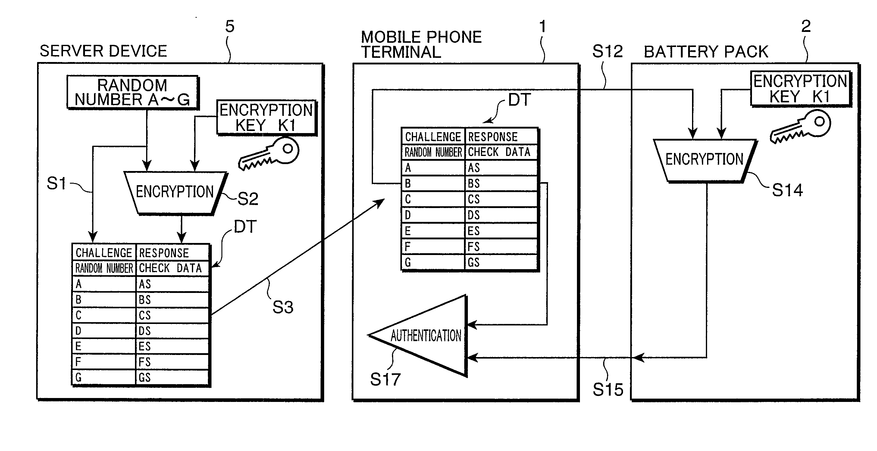
[0013]In this case, the authentication data used for authentication is transmitted from the server device and received by the authentication device. Further, this authentication data is transmitted to the device to be authenticated by the authentication device. By the authentication device, the authentication of the authentication device is made based on the reply data returned by the device to be authenticated and the check data obtained by encrypting the authentication data using the preset encryption method and encryption key. Accordingly, the authentication device needs not include a circuit for generating authentication data and encryption and decryption circuits for encrypting and decrypting the authentication data, and can authenticate the device to be authenticated while a circuit scale increase in the authentication device is suppressed.

Problems solved by technology

However, there are many manufacturers who manufacture battery packs and charging devices for charging battery packs illegally or without any permission, and the charging devices manufactured by such manufacturers are very poor in their quality in many cases.
Thus, it has become a major issue to discern whether or not a charging device is the illegally manufactured one and to prevent the damage of a secondary battery and an occurrence of a disaster in the case of charging the secondary battery by such a charging device.
However, according to this conventional technology, the ID number stored in the battery pack can be relatively easily obtained if communication data transmitted and received between the battery pack and the device main unit are deciphered and there still remains a problem that the battery pack is easily counterfeited using the ID number obtained from such communication data.
This requires an increase in the circuit scale and the tamper proofness of the hardware itself of such circuits, leading to a problem of a cost increase.

Method used


Image

  • Authentication system and authentication device
  • Authentication system and authentication device
  • Authentication system and authentication device

Examples


first embodiment

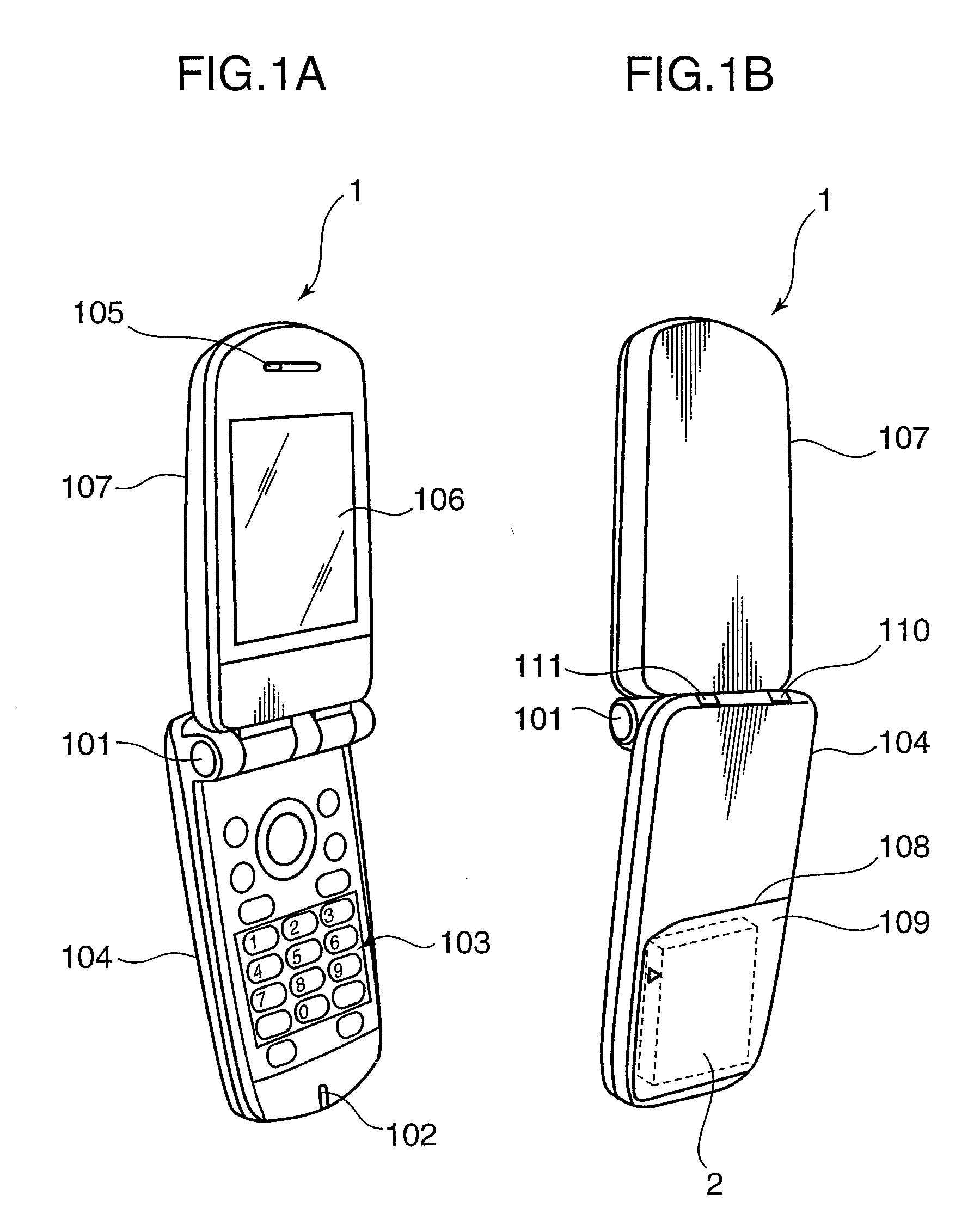
[0039]FIG. 1 are external perspective views showing exemplary constructions of a mobile phone terminal and a battery pack according to a first embodiment of the invention. The mobile phone terminal 1 shown in FIG. 1 is constructed to be foldable substantially in its center by the presence of a hinge 101, and FIG. 1 show a state where the mobile phone terminal 1 is opened. FIG. 1A is a front view in the state where the mobile phone terminal is opened, and FIG. 1B is a rear view in the state where the mobile phone terminal is opened.

[0040]As shown in FIG. 1A, the mobile phone terminal 1 is constructed such that a holding part 104 including a microphone 102 for converting user's voices into electrical signals and operation keys 103 for receiving the operation of the user and a display part 107 including a speaker 105 for outputting sounds and a liquid crystal display 106 are connected via the hinge 101.

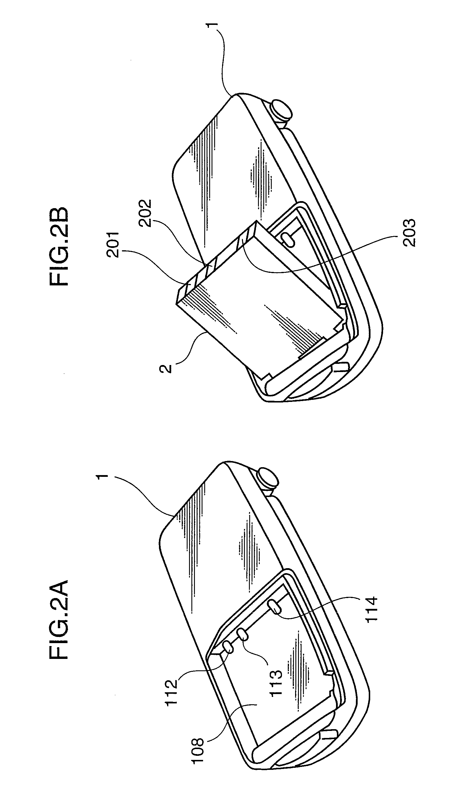
[0041]Further, as shown in FIG. 1B, a detachable cover 108 is mounted on the rear su...

second embodiment

[0118]Next, an authentication system 3a and a mobile phone terminal 1a according to a second embodiment of the present invention are described. The schematic construction of the authentication system 3a is shown in FIG. 4 similar to the authentication system 3.

[0119]FIG. 15 is a block diagram showing an exemplary electrical construction of a server device 5a used in the authentication system 3a. The server device 5a shown in FIG. 15 and the server device 5 shown in FIG. 5 differ in that the server device 5a further includes a server-side authenticating section 530 in a server controller 52a and a server-side transmitting section 525a performs a different operation.

[0120]FIG. 16 is a block diagram showing an exemplary electrical construction of the mobile phone terminal 1a used in the authentication system 3a. The mobile phone terminal 1a shown in FIG. 16 and the mobile phone terminal 1 shown in FIG. 6 differ in that a terminal controller 14a includes neither the authenticating-side ...

third embodiment

[0142]Next, an authentication system 3b according to a third embodiment of the present invention is described. The schematic construction of the authentication system 3b is shown in FIG. 4 similar to the authentication system 3. FIG. 19 is a conceptual diagram showing an exemplary electrical construction of the authentication system 3b according to the third embodiment of the present invention. The authentication system 3b shown in FIG. 19 includes a server device 5b, a mobile phone terminal 1 and a battery pack 2b.

[0143]FIG. 20 is a block diagram showing an exemplary construction of the server device 5b. The server device 5b shown in FIG. 20 differs from the server device 5 shown in FIG. 5 in further including an ID tag (identification tag) IC (integrated circuit) 54 (second integrated circuit) and an IC socket 55 (connecting portion), including no server-side encryption key storage 521 and including a check data generating section 524b instead of the check data generating section...


PUM


Abstract

An authentication system is provided with a server device for generating a random number used for authentication and check data obtained by encrypting the random number using an encryption key, an authentication device for authenticating a device to be authenticated by transmitting the random number transmitted from the server device to the device to be authenticated and comparing reply data transmitted from the device to be authenticated with check data transmitted from the server device, and the device to be authenticated for encrypting the random number transmitted from the authentication device using the encryption key and transmitting the encrypted random number as reply data.

Description

TECHNOLOGICAL FIELD[0001]The present invention relates to an authentication system for authenticating a device to be authenticated and an authentication device used for authentication.BACKGROUND ART[0002]In recent years, the energy densities of batteries have been significantly increased. However, there are many manufacturers who manufacture battery packs and charging devices for charging battery packs illegally or without any permission, and the charging devices manufactured by such manufacturers are very poor in their quality in many cases. Thus, it has become a major issue to discern whether or not a charging device is the illegally manufactured one and to prevent the damage of a secondary battery and an occurrence of a disaster in the case of charging the secondary battery by such a charging device.[0003]Accordingly, there is known technology for determining whether a battery pack is the legitimate one by giving an ID number to a battery pack and by causing the device main unit ...

Claims


Application Information

Patent Timeline
IPC IPC(8): H04L9/32G06F21/20H04L9/08H04W12/00H04W52/00H04W88/00H04W88/18
CPCG06F21/31G06F2221/2129H04L9/3271H04L2209/80H04L9/0891H04L9/0894H04L63/0807
Inventor MORI, IICHIRONAKASHIMA, SHOTA
Owner PANASONIC CORP
Learn More