Apparatus for positioning and splitting wood

a technology for positioning and splitting wood, applied in the field of wood splitters, can solve the problems of devices not addressing the problem of moving wood to the splitter or moving

Inactive Publication Date: 2009-11-26
M&G POWER ATTACHMENTS
View PDF27 Cites 4 Cited by
  • Summary
  • Abstract
  • Description
  • Claims
  • Application Information

AI Technical Summary

Benefits of technology

[0005]The instant invention provides an apparatus that is easily and reversibly coupled to a backhoe boom or the like in place of the bucket thereof, which apparatus is more readily observed in operation and which apparatus permits an improved means of moving wood before and after splitting, and which is capable of moving not only wood but branches and brush to, for example, brush chipper. More specifically, the instant invention is an apparatus for positioning and splitting wood, comprising: a beam having a first end and a second end, the beam having a longitudinal axis; a wood splitting blade attached at or near the first end of the beam; a workpiece slidably attached to the beam such that when wood is positioned between the splitting blade and the workpiece and the workpiece is slid in the direction of the longitudinal axis of the beam toward the splitting blade, the wood is forced into the splitting blade to split the wood; and a stationary jaw member attached at or near the second end of the beam so that when the apparatus is attached to the boom of a backhoe or excavator in place of the bucket thereof, wood can be grasped between the stationary jaw member and a jaw member attached to the boom of the backhoe or excavator so that the wood can be positioned by movement of the apparatus.

Problems solved by technology

However, such devices did not address the problem of moving wood to the splitter or moving the split wood to, for example, the bed of a truck.

Method used


Image

  • Apparatus for positioning and splitting wood
  • Apparatus for positioning and splitting wood
  • Apparatus for positioning and splitting wood

Examples


Embodiment Construction

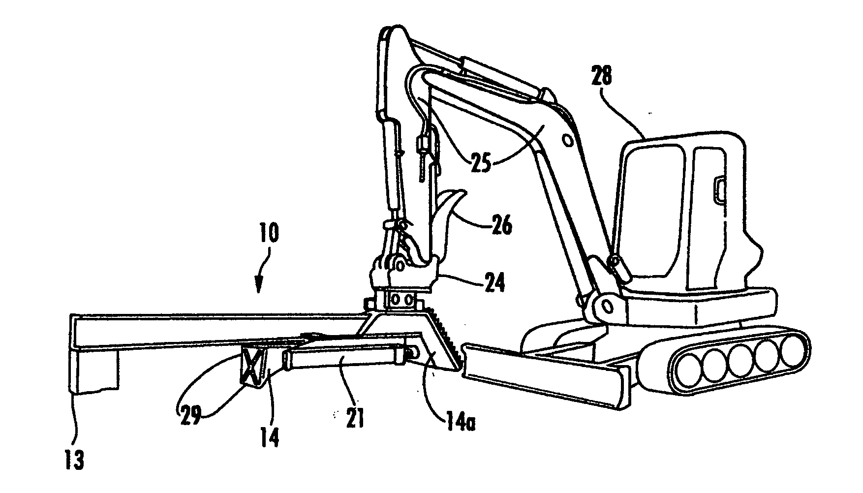
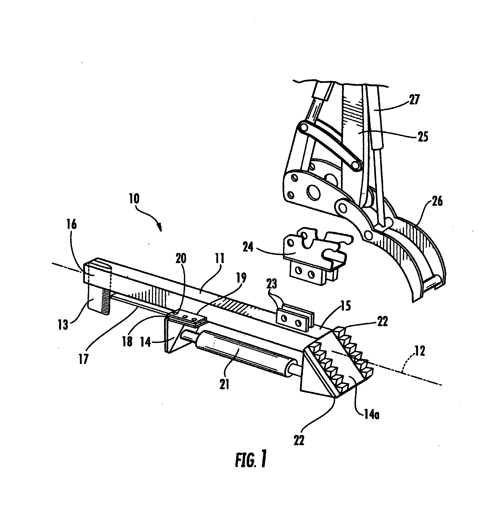
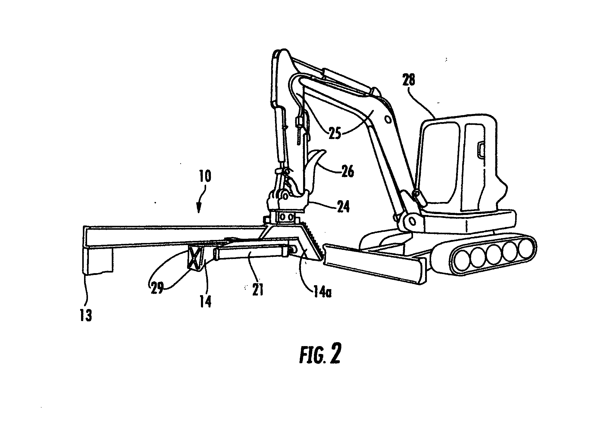
[0014]Referring now to FIG. 1, therein is shown a perspective view of a highly preferred apparatus 10 for positioning and splitting wood according to the instant invention. The apparatus 10 comprises a beam 11 having a first end 16 and a second end 15, the beam 11 having a longitudinal axis 12. The beam 11 is a steel box beam. A steel wood splitting blade 13 is welded to the first end 16 of the beam 11. A steel workpiece 14 is slidably attached to the beam 11 such that when wood is positioned between the splitting blade 13 and the workpiece 14 and the workpiece 14 is slid in the direction of the longitudinal axis 12 of the beam 11 toward the splitting blade 13, the wood is forced into the splitting blade 13 by hydraulic ram 21 to split the wood. A steel flange 17 is welded to both sides of the beam 11. A steel spacer 18 which is slightly thicker than the flange 17 is held in place on each side of the beam 11 by top plate 19 and bolts 20. A stationary jaw member in the form of a stee...


PUM


Abstract

Apparatus for positioning and splitting wood. The apparatus includes: a beam having a longitudinal axis; a wood splitting blade attached at or near an of the beam; a workpiece slidably attached to the beam such that when wood is positioned between the splitting blade and the workpiece and the workpiece is slid in the direction of the longitudinal axis of the beam toward the splitting blade, the wood is forced into the splitting blade to split the wood; and a stationary jaw member attached at or near one end of the beam so that when the apparatus is attached to the boom of a backhoe or the like in place of the bucket thereof, wood can be grasped between the stationary jaw member and a jaw member attached to the boom of the backhoe or the like so that the wood can be positioned by movement of the apparatus.

Description

BACKGROUND OF THE INVENTION[0001]The instant invention is in the field of wood splitters and more specifically the instant invention is in the field of wood splitters that have the additional capability to move and position wood to be split.[0002]In the logging and tree service industry many tools have been developed to make it easier to process wood once the trees have been trimmed or cut down. In particular, attempts have been made to provide improved wood splitting devices. For example, the well known trailer mounted hydraulic wood splitting devices (such as the device described in U.S. Pat. No. 4,310,039) were a significant improvement. However, such devices did not address the problem of moving wood to the splitter or moving the split wood to, for example, the bed of a truck. A number of devices have been disclosed that can be used to both position and split wood. The devices disclosed in US 2003 / 0155037 and U.S. Pat. No. 6,609,547 comprises a hydraulic wood splitter suspended ...

Claims


Application Information

Patent Timeline
IPC IPC(8): B27L7/00
CPCB27L7/00
Inventor GILMET, MATHEW A.
Owner M&G POWER ATTACHMENTS
Why Eureka
Try Eureka