
Microjet creation and control of shock waves

a technology of shock waves and microjets, applied in the direction of air-flow influencers, marine propulsion, vessel construction, etc., can solve the problems of increased deceleration, insufficient control of such waves, and actual damage, and achieve the effect of increasing the flow rate of microjets

Inactive Publication Date: 2009-11-26
FLORIDA STATE UNIV RES FOUND INC
View PDF7 Cites 23 Cited by
  • Summary
  • Abstract
  • Description
  • Claims
  • Application Information

AI Technical Summary

Benefits of technology

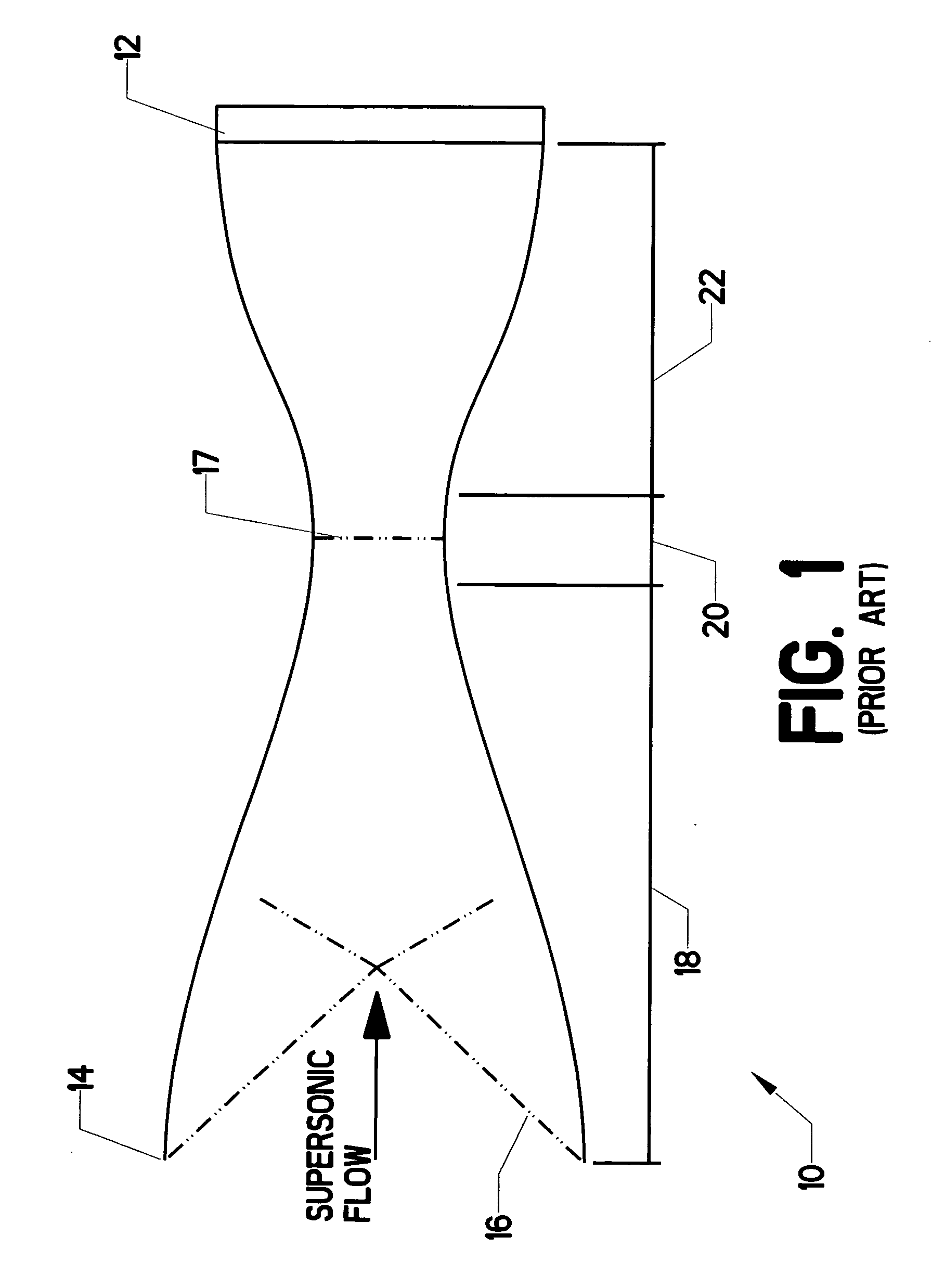
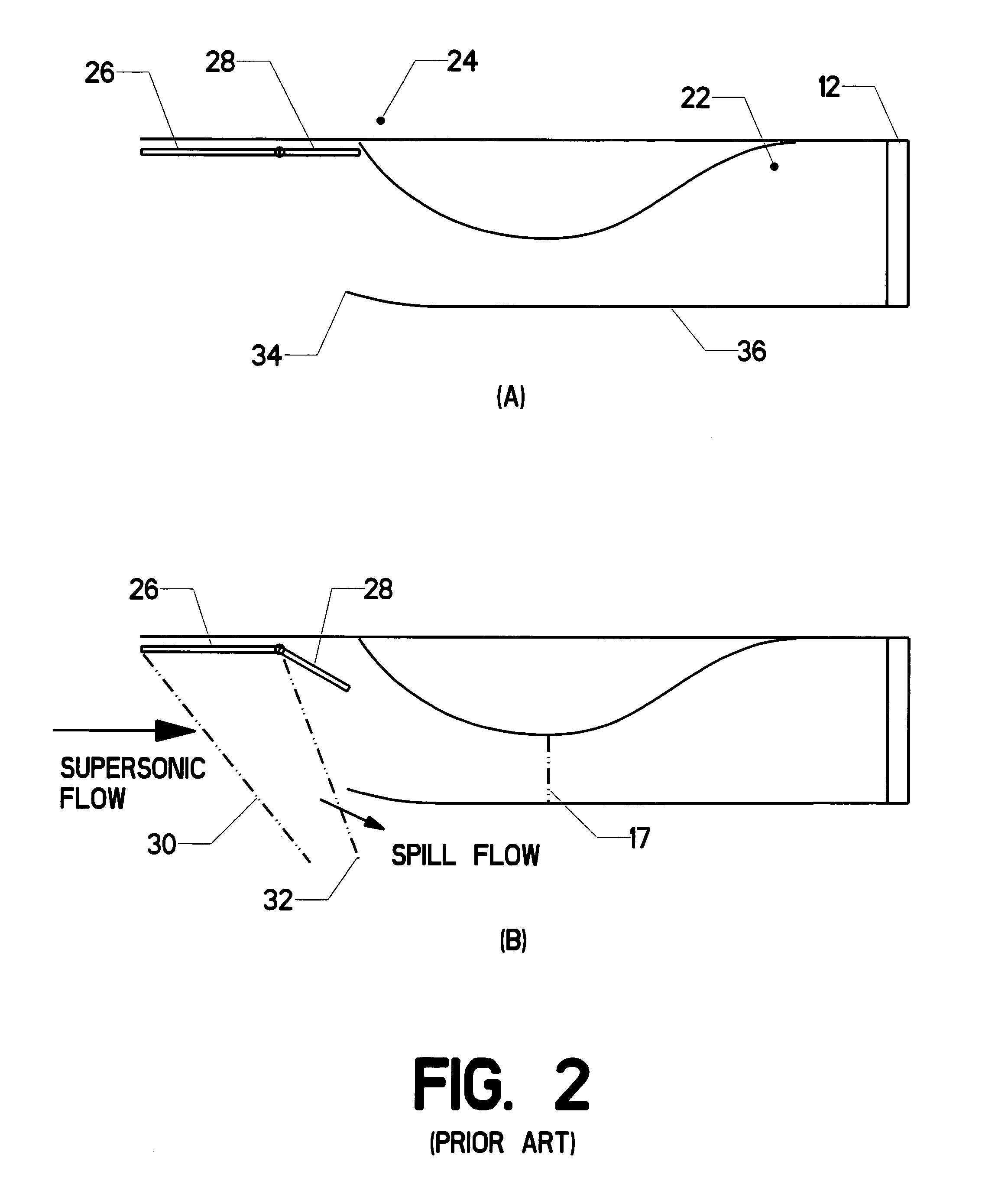
[0029]The present invention comprises the use of one or more microjets to create and / or control oblique shock waves. The introduction of microjet flow into a supersonic stream creates an oblique Mach wave. This wave can be strengthened—by increasing microjet flow rate or the use of many microjets in an array—in order to form an oblique shock. Such an oblique shock can be used to decelerate flow in a jet aircraft engine inlet in a controlled fashion. Adjusting the pressure ratio across the microjet actually alters the angle of the oblique shock. Thus, the use of microjets allows decelerating shock waves in an inlet engine to be properly positioned and controlled.

Problems solved by technology

Shock waves striking the ground create a “sonic boom,” which may at best cause annoyance and at worst cause actual damage.
The nature of shock waves in the inlets of jet aircraft engines has been thoroughly studied, though the control of such waves has not been thoroughly developed.
The oblique shock waves tend to reflect from the contracting walls of the compression section, creating additional deceleration.
The flow entering and passing through the compression section is more complex, more variable, and more difficult to predict.
In fact, variable incoming and engine flow states may cause “inlet unstart,” a phenomenon wherein the normal shock travels forward into the compression section and may even be ejected out the front of the intake.
Such a condition produces drastic flow losses and may flame out the engine.
The flow velocities may be even higher in the supercritical state but the pressure recovery will be reduced, which is generally undesirable.
This is generally a dangerous condition since it may cause intake unstart.
Concerns about sonic booms obviously make this approach less desirable.
However, if moving ramps are used in this intake, they may well be visible to radar when deployed.
As mentioned previously, a mixed compression inlet tends to produce an external oblique shock and a resulting sonic boom.

Method used


Image

  • Microjet creation and control of shock waves
  • Microjet creation and control of shock waves
  • Microjet creation and control of shock waves

Examples


Embodiment Construction

[0043]The present invention contemplates the injection of relatively small masses of compressed fluid through one or more microjets. A microjet is defined as a small expansion nozzle. A typical size is a diameter of 400 micrometers, or about 0.016 inches. FIG. 5 shows a sectional elevation view of a single microjet 44. Settling chamber 46 provides a volume of pressurized gas (such as nitrogen or air). Microjet 44 is a very small expansion nozzle which vents the pressurized gas to the surrounding atmosphere. The microjet preferably has a shape such as shown (a DeLaval expansion profile) but may also have a simpler profile including straight side walls. The input stagnation pressure to each microjet or array of microjets is preferably controlled within a reasonable variation. As one example—suited to a particular application—the stagnation pressure could be controlled within a tolerance of about 7 kPa or 1 psi. The microjet is shown as normal to the surface it vents through, which is ...


PUM


Abstract

A method of using one or more microjets to create and / or control oblique shock waves. The introduction of microjet flow into a supersonic stream creates an oblique shock wave. This wave can be strengthened—by increasing microjet flow rate or the use of many microjets in an array—in order to form an oblique shock. Such an oblique shock can be used to decelerate flow in a jet aircraft engine inlet in a controlled fashion, thus increasing pressure recovery and engine efficiency while reducing flow instability. Adjusting the pressure ratio across the microjet actually alters the angle of the oblique shock. Thus, the use of microjets allows decelerating shock waves in an inlet engine to be properly positioned and controlled. Microjet arrays can also be used to ameliorate shock waves created by external aircraft surfaces, such as sensor pods and weapons. Microjets placed forward of any external protuberance can convert a single substantial shock wave into a series of much milder waves which will not produce unwanted external effects, such as strong sonic booms.

Description

CROSS-REFERENCES TO RELATED APPLICATIONS[0001]This application is a non-provisional application claiming the benefit, pursuant to 37 C.F.R. §1.53 (c), of an earlier-filed provisional application. The provisional application was filed on May 21, 2008 and was assigned application Ser. No. 61 / 128,330.STATEMENT REGARDING FEDERALLY SPONSORED RESEARCH OR DEVELOPMENT[0002]Not applicable.MICROFICHE APPENDIX[0003]Not ApplicableBACKGROUND OF THE INVENTION[0004]1. Field of the Invention[0005]This invention relates to the field of flow control in a compressible flow. More specifically, the invention comprises the use of properly placed microjets to create and / or control shock waves in supersonic flow.[0006]2. Description of the Related Art[0007]Shock waves are created whenever an object moves through a compressible fluid at a velocity equal to or greater than the speed of sound in the compressible fluid. Compressible flow in air is of obvious interest, and this application deals primarily with ...

Claims


Application Information

Patent Timeline
Patent Type & Authority Applications(United States)
IPC IPC(8): F02M35/10B64D33/02
CPCB64D33/02B64D2033/026B64D2033/0226Y10T137/0645Y10T137/0318
Inventor ALVI, FARRUKH S.
Owner FLORIDA STATE UNIV RES FOUND INC
Learn More