Devices for creating passages and sensing for blood vessels

Inactive Publication Date: 2009-11-19
BRONCUS MEDICAL
View PDF106 Cites 49 Cited by
  • Summary
  • Abstract
  • Description
  • Claims
  • Application Information

AI Technical Summary

Benefits of technology

[0009]The device allows for sensing blood vessels in tissue, and allows for creation of a passage or opening without moving the sensing element. The device includes a catheter member having a near end, a far end, and a lumen extending therethrough, a dilation member within the lumen and having a shaft, the shaft having a distal tip and a non-distensible expandable member adjacent to the distal tip, the dilation member being slidably located within the catheter member, a sensing assembly located at the far end of the catheter member, and where the non-distensible expandable member is moveably located within the lumen independent of the sensing assembly, such that when the sensing assembly contacts tissue, the dilation member may be advanced out of the catheter member and into the tissue without removing the sensing member from the tissue.
[0012]The sensing assembly is used to scan the tissue to minimize causing undesirable injury to the patient. As discussed below, any number of sensing modes may be incorporated into the device. However, it was found that Doppler ultrasound transducer assemblies perform acceptably when sensing for blood vessels within tissue. In certain variations, the sensing assembly may be configured to puncture the tissue and create the opening. However, in other variations, the sensing assembly will have a blunted tip to minimize undesirable tissue damage.
[0013]In variations of the device, the sensing assembly is offset from an axis of the catheter and / or dilation assembly. Doing so improves the ability of the sensing assembly to contact tissue surfaces when the device is advanced along body conduits. In addition, this offset feature improves the ability to see the tip of the sensing assembly when the device is used with a scope type device.

Problems solved by technology

The problem is compounded when accounting for the tidal motion of lungs.
For example, because the target site moves due to the tidal motion of the lungs (as a result of the mechanics of breathing), it is difficult to visually identify an area that was previously scanned unless the scanning device remains relatively stationary against the tissue.
Moreover, the difficulty increases when considering that the procedure takes place through the camera of a bronchoscope or endoscope.

Method used


Image

  • Devices for creating passages and sensing for blood vessels
  • Devices for creating passages and sensing for blood vessels
  • Devices for creating passages and sensing for blood vessels

Examples


Embodiment Construction

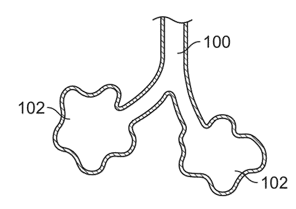
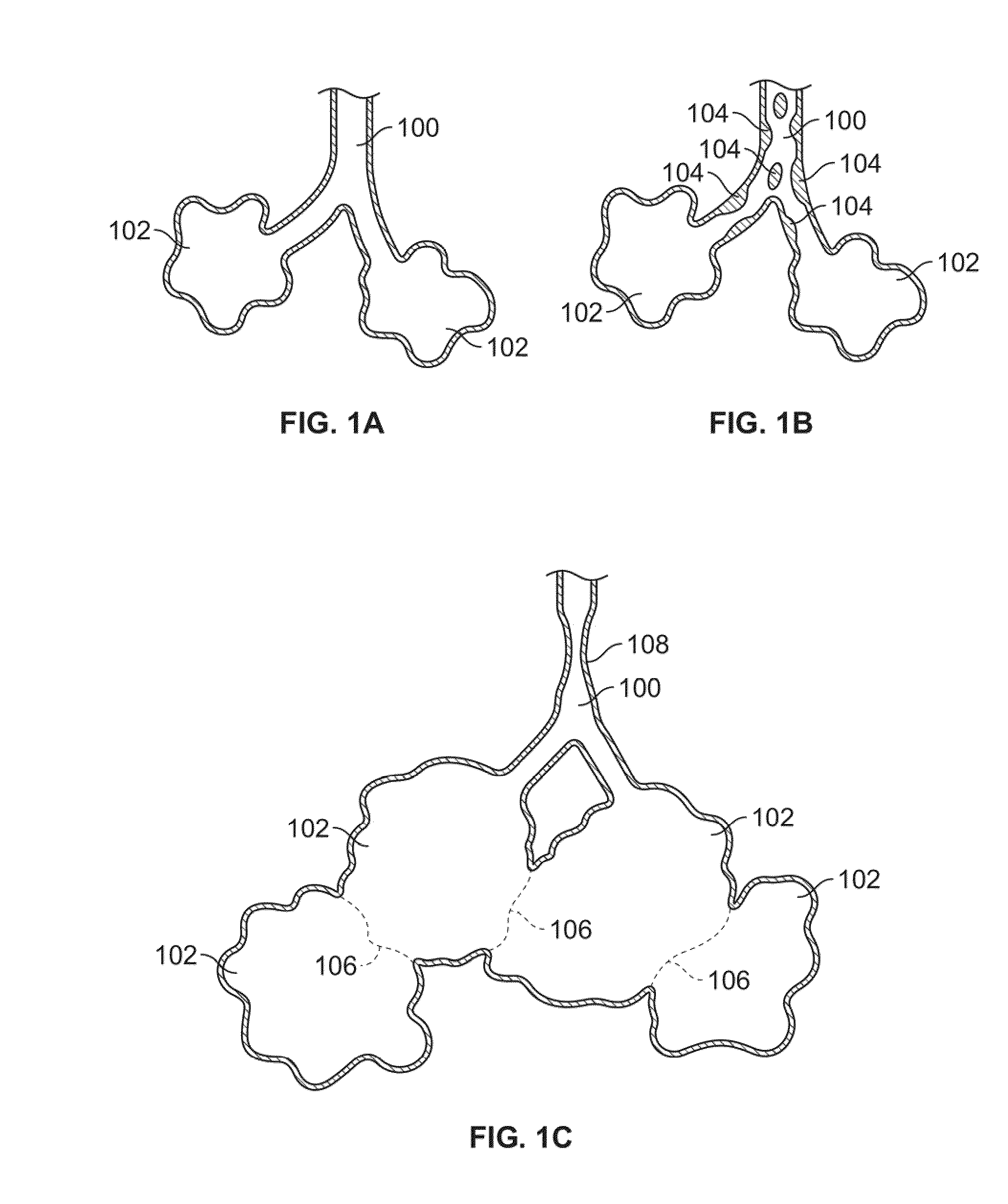
[0031]FIG. 1A shows a simplified illustration of a natural airway 100 which eventually branches to a blood gas interface 102. FIG. 1B illustrates an airway 100 and blood gas interface 102 in an individual having COPD. The obstructions 104 (e.g., excessive mucus resulting from COPD, see above) impair the passage of gas between the airways 100 and the interface 102. FIG. 1C illustrates a portion of an emphysematous lung where the blood gas interface 102 expands due to the loss of the interface walls 106 which have deteriorated due to a bio-chemical breakdown of the walls 106. Also depicted is a constriction 108 of the airway 100. It is generally understood that there is usually a combination of the phenomena depicted in FIGS. 1A-1C. More usually, the states of the lung depicted in FIGS. 1B and 1C are often found in the same lung.

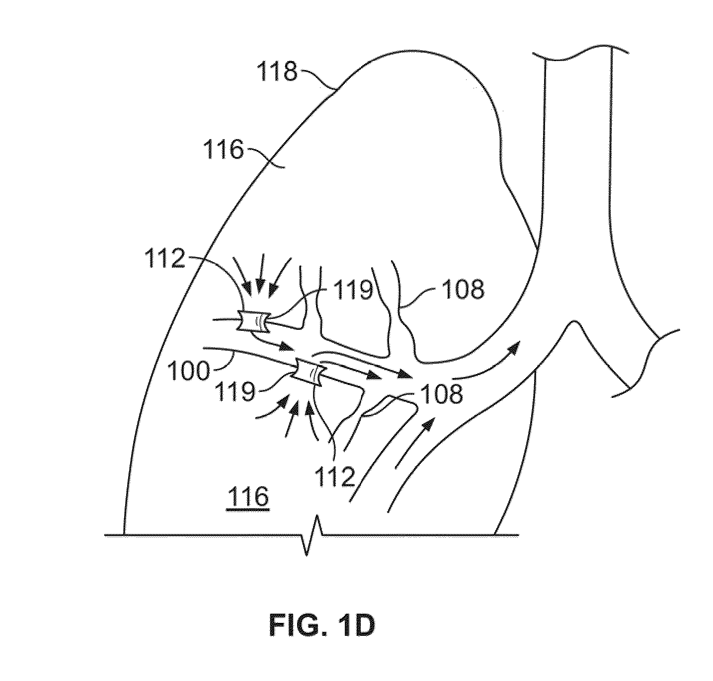
[0032]As will be explained in greater detail below, the production and maintenance of collateral openings or channels through airway walls permits expired air...


PUM


Abstract

Devices and methods are disclosed for creating passages in tissue and detecting blood vessels in and around the passages. The devices may be used to create opening in tissue without removing a sensing assembly from the tissue. The devices herein may be used for altering gaseous flow within a lung to improve the expiration cycle of an individual, particularly individuals having Chronic Obstructive Pulmonary Disease (COPD). In addition, the devices may be used to sample tissue during biopsy or other medical procedures where perforating a blood vessel could result in injury to a patient.

Description

CROSS-REFERENCE TO RELATED APPLICATIONS[0001]This application is a continuation of International Application No. PCT / US2007 / 084330, filed Nov. 9, 2007 which claims priority to U.S. Provisional Application No. 60 / 867,076, filed Nov. 22, 2006; both applications are incorporated herein by reference in their entireties.FIELD OF THE INVENTION[0002]The invention is directed to devices for sensing movement within tissue, and then creating passages in the tissue. In one variation, sensing movement may comprise sensing for the presence or absence of blood vessels. Variations may include further detecting for these blood vessels in the passages created by the device.BACKGROUND OF THE INVENTION[0003]It was found that creation of collateral channels in COPD patients allowed expired air to pass out of the lungs and decompressed hyper-inflated lungs. Such methods and devices for creating and maintaining collateral channels are discussed in U.S. Pat. No. 6,692,494; U.S. patent application Ser. Nos...

Claims


Application Information

Patent Timeline
IPC IPC(8): A61B8/14A61M29/00
CPCA61B5/489A61B8/06A61B8/12A61B17/3478A61B19/46A61B8/445A61B2017/00809A61B2017/22051A61B2017/22077A61B2019/528A61B2017/00252A61B2090/3784A61B90/06
Inventor GWERDER, ERIC J.KEAST, THOMAS M.ROSCHAK, EDMUND J.
Owner BRONCUS MEDICAL
Why Eureka
Try Eureka