
Rankine cycle heat recovery methods and devices

a heat recovery and cycle technology, applied in the direction of mechanical equipment, machines/engines, electric generator control, etc., can solve the problems of inability to directly feed low-quality steam to the pump, never being used, and being impractical to design a pump, etc., to achieve the effect of reducing frictional losses and high rotational velocity

Inactive Publication Date: 2009-11-12
DANFOSS AS
View PDF17 Cites 93 Cited by
  • Summary
  • Abstract
  • Description
  • Claims
  • Application Information

AI Technical Summary

Benefits of technology

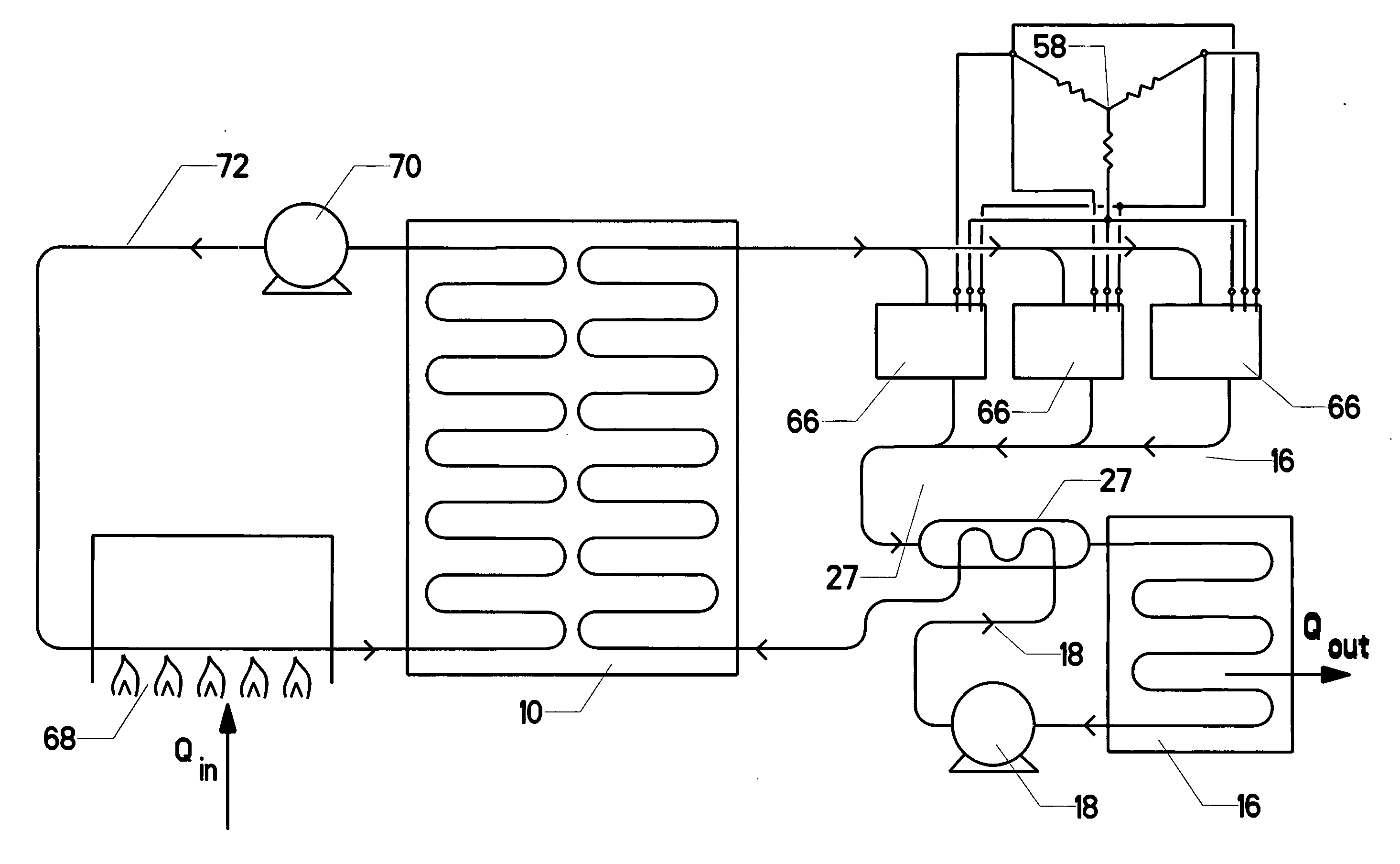
[0034]The present invention is an integrated expansion turbine / electrical generator assembly (collectively referred to as a “turbo-generator”) suitable for use in waste heat recovery and similar applications. The turbo-generator uses a common shaft mounting a one or more stage expansion turbine and an electrical generator. Oilless axial and thrust bearings are used to hold the common shaft in its proper position within a fixed housing. The oilless bearings are preferably of the magnetic or foil type. They minimize frictional losses, allowing the common shaft to spin at a very high rotational velocity.
[0036]The turbo-generator is preferably of modest size and mass, so that it may be easily transported. It is also preferably of modular design, so that two or more turbo-generators can be run in parallel. In some applications, it is also preferable to run two or more such turbo-generators in a series connection so that they can accommodate multi-expansion Rankine cycles.

Problems solved by technology

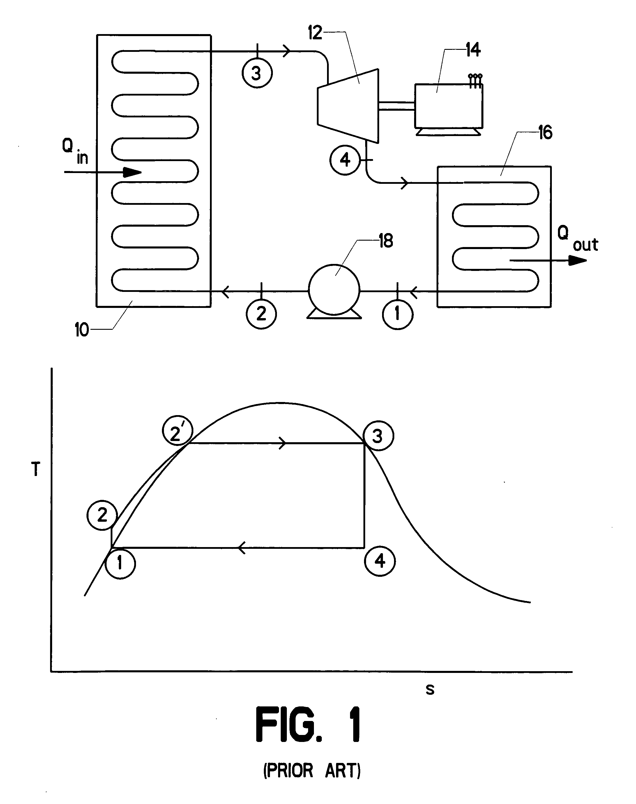
The low quality steam cannot be fed directly to the pump, since it is impractical to design a pump which will effectively handle a mixture of liquid and vapor.
This is, of course, never actually the case.
Heat is always transferred in these processes and frictional losses always occur.
However, in steam cycles, the ability to increase the expansion ratio is always limited.
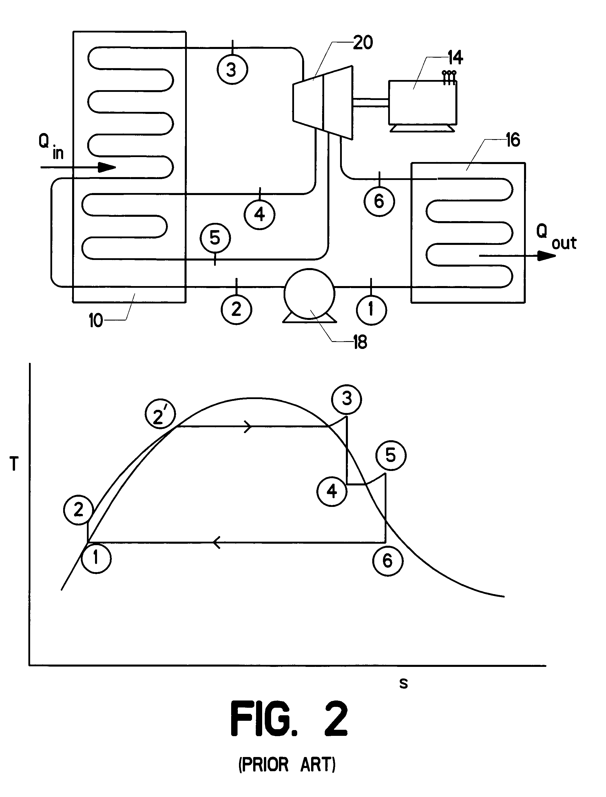
The water droplets—in turn—can impinge upon the turbine blades and substantially reduce the turbine's life.
Thus, when steam is used as a working fluid, the cycle designer generally reduces the turbine expansion ratio well below what would otherwise be optimal.
However, it also increases complexity and cost.
FIG. 3 shows a variation on the Rankine cycle which is generally referred to as the “regenerative cycle.” When using superheated steam turbine cooling can be a problem.
Enough high pressure steam is added to significantly raise the temperature of the resulting combination, but not enough to produce a significant quantity of vapor.
Rankine cycles used in actual power production tend to be still more complex.
However, the use of steam as a working fluid is not generally suitable for these applications.
Such a low temperature heat source simply cannot impart substantial specific energy to steam.
This results from steam's relatively low molecular weight.
This ultimately becomes impractical.
They have also employed components designed for steam operation—particularly expensive components such as turbines.
The result has not been optimal, since organic working fluids are inherently different from steam.
A near-vertical slope can be achieved, though such an azeotrope's long term thermal stability is questionable.
No single working fluid will be suitable for all applications.
These engines have been relatively expensive to build, however.
As the energy output is modest, the payback period for constructing such a facility can be lengthy.

Method used


Image

  • Rankine cycle heat recovery methods and devices
  • Rankine cycle heat recovery methods and devices
  • Rankine cycle heat recovery methods and devices

Examples


Embodiment Construction

[0061]FIG. 6 shows an integrated expansion turbine 12 and generator 28, which are collectively referred to as turbo-generator 66. The turbo-generator is specially configured for efficient use with heat recovery cycle engines. Though it is not limited to organic Rankine cycle engines, many of its applications will lie in that field.

[0062]The turbo-generator is preferably able to operate over a wide range of rotational speeds and expansion ratios. It is preferably also able to handle a variety of working fluids, including fairly aggressive chemicals such as toluene. Common shaft 30 extends from one end of the device to the other. It is supported by two or more bearings, which are oilless bearings, preferably of the foil or electromagnetic type. The bearings can be located in a variety of suitable positions, such as front bearing 36, middle bearing 37, and rear bearing 40 in FIG. 6.

[0063]If electromagnetic bearings are used, then the common shaft will likely be suspended using only two...


PUM


Abstract

An integrated expansion turbine / electrical generator assembly (collectively referred to as a “turbo-generator”) suitable for use in waste heat recovery and similar applications. The turbo-generator uses a common shaft mounting a one or more stage expansion turbine and a homopolar electrical generator. Magnetic levitating axial and thrust bearings are used to hold the common shaft in its proper position with a fixed housing. The magnetic bearings minimize frictional losses, allowing the common shaft to spin at a very high rotational velocity. Sensor rings continually monitor the common shaft's position. This information is used by control electronics to regulate the magnetic bearings in order to hold the rotating shaft's position. Electrical energy is extracted from the rotating shaft in the form of a direct current. Preferably integrated power-switching electronics are used to generate single or three-phase AC power, which can be phase-matched to an existing power grid or other application.

Description

CROSS-REFERENCES TO RELATED APPLICATIONS[0001]Pursuant to 37 C.F.R. §1.53(c), this is a non-provisional application claiming the benefit of an earlier-filed provisional application. The provisional application was filed on May 6, 2008 and was assigned Ser. No. 61 / 126,603. It listed the same inventor.STATEMENT REGARDING FEDERALLY SPONSORED RESEARCH OR DEVELOPMENT[0002]Not Applicable.MICROFICHE APPENDIX[0003]Not ApplicableBACKGROUND OF THE INVENTION[0004]1. Field of the Invention[0005]The present invention relates to the fields of power generation and waste heat recovery. More specifically, the invention comprises a combined expansion turbine and electrical generator configured for use in waste heat recovery Rankine cycles.[0006]2. Description of the Related Art[0007]Many common industrial machines must reject “waste heat” to the surrounding atmosphere in order to operate. While this phenomenon is well understood by those familiar with the laws of thermodynamics, some simple examples ...

Claims


Application Information

Patent Timeline
IPC IPC(8): F02B63/00F01P3/22F01P7/00F02B33/00F01K25/08F01D15/10
CPCF01N5/02F01P3/22F02B39/085F02G5/04F01K23/065Y02T10/16Y02T10/166F01K15/02F02G2260/00Y02T10/12
Inventor CONRY, RONALD DAVID
Owner DANFOSS AS
Learn More