
Low-profile frequency selective surface based device and methods of making the same

a frequency selective surface and low-profile technology, applied in the direction of slot antennas, antennas, antennas, etc., can solve the problems of unsatisfactory sensitivity of the response to the angle of incidence of radiation, and the physical thickness tsub>100 /sub> of conventional multi-layer fss b>100/b> limits its application, so as to achieve the effect of high quality factor

Inactive Publication Date: 2009-11-05
UNIV OF CENT FLORIDA RES FOUND INC
View PDF7 Cites 62 Cited by
  • Summary
  • Abstract
  • Description
  • Claims
  • Application Information

AI Technical Summary

Benefits of technology

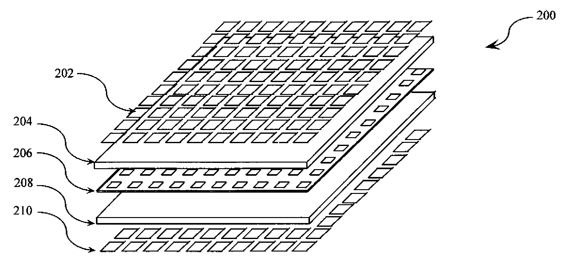
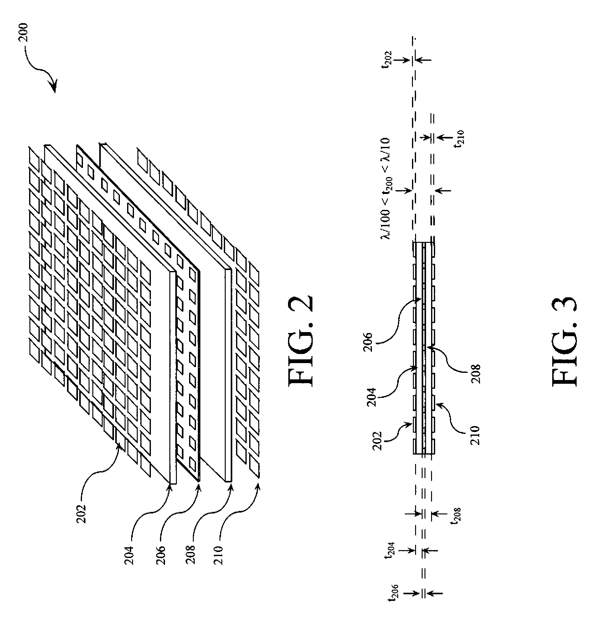
"The present invention concerns devices that process electromagnetic waves using frequency selective surfaces (FSSs). The invention includes at least three FSSs, with one FSS having a higher primary resonant frequency than the other two FSSs. A high quality factor (Q) FSS is interposed between the first and second FSSs, with a loaded quality factor of at least thirty at its primary resonant frequency. The FSS-based device also includes dielectric layers with an electrical thickness of less than a twentieth of a wavelength, making the device low-profile. The technical effect of the invention is to provide low-profile devices with improved performance and reduced size."

Problems solved by technology

For example, the significant physical thickness t100 of the conventional FSS 100 results in an undesirable sensitivity of its response to the angle of incidence of the radiation.
Also, the physical thickness t100 of conventional multi-layer FSS 100 limits its applications, including applications where conformal FSSs are required.

Method used


Image

  • Low-profile frequency selective surface based device and methods of making the same
  • Low-profile frequency selective surface based device and methods of making the same
  • Low-profile frequency selective surface based device and methods of making the same

Examples


example

[0067]A third-order FSS 200 having an equivalent circuit 900 was designed using design process 1000. The circuit elements of the equivalent circuit 900 used in the design process 1000 were defined as: C1=22.2 pF; C2=0.38 pF; L1=108 pH; L2=147 pH; Z0=377Ω; Z1=254Ω; 1=0.5 mm; and ∈r=2.2. The physical and geometrical parameters for the third-order FSS 900 obtained during the design process 1000 were defined as: Dx=5.5 mm; Dy=5.5 mm; t200=0.5 mm; ∈r=2.2; s=60 μm; and Dap=1.46 mm.

[0068]The frequency response between four and sixteen gigahertz (4 GHz-16 GHz) of the third-order FSS 200 obtained from FWEM simulations is shown graphically in FIG. 12. The frequency response of the equivalent circuit 900 obtained from CB simulations is also shown graphically in FIG. 12. As shown in FIG. 12, the equivalent circuit 900 accurately predicted the frequency response of the third-order FSS 200. A calculated frequency response of the third-order FSS 200 for non-normal angles of incidence (θ=15°, 30°, ...


PUM


Abstract

A frequency selective surface-based (FSS-based) device (200) for processing electromagnetic waves providing at least a third-order response. The FSS-based device includes a first FSS (202), a second FSS (210), and a high quality factor (Q) FSS (206) interposed between the first and second FSSs. A first dielectric layer (204) and a second dielectric layer (208) separate the respective FSS layers. The first and second FSSs have first and second primary resonant frequencies, respectively. The high Q FSS has a lower primary resonant frequency relative to the first and second primary resonant frequencies. The overall electrical thickness of the PSS device can be <λ / 10. The high Q FSS has a loaded quality factor of at least thirty at the lower primary resonant frequency.

Description

BACKGROUND[0001]1. Statement of the Technical Field[0002]The invention concerns frequency selective surfaces (FSSs). More particularly, the invention concerns FSS based devices and methods of making the same.[0003]2. Background[0004]FSSs are surface constructions generally comprising a periodic array of electrically conductive elements. As known in the art, in order for its structure to affect electromagnetic waves (EMs), the FSS must have structural features at least as small, and generally significantly smaller, as compared to the wavelength of the electromagnetic radiation it interacts with.[0005]FSSs are typically used in a variety of antenna applications. Such antenna applications include, but are not limited to, radome applications, Dichroic sub-reflector applications, reflect array lens applications, spatial microwave applications, optical filter applications, radio frequency identification (RFID) tag applications, collision avoidance applications, waveguide applications, and...

Claims


Application Information

Patent Timeline
Patent Type & Authority Applications(United States)
IPC IPC(8): H01Q13/10H01Q1/28H01Q1/34
CPCH01Q1/286H01Q1/34H01Q13/10H01Q15/006H01Q21/064H01Q21/24H01Q15/0026H01Q13/16
Inventor BEHDAD, NADER
Owner UNIV OF CENT FLORIDA RES FOUND INC
Learn More