Liquid cooling heat dissipating device
a heat dissipating device and liquid cooling technology, applied in the direction of semiconductor devices, lighting and heating apparatus, basic electric elements, etc., can solve the problems of significant impact on the efficiency of the chip, damage to the chip, poor expandability, etc., to improve the expandability and assembly convenience.
- Summary
- Abstract
- Description
- Claims
- Application Information
AI Technical Summary
Benefits of technology
Problems solved by technology
Method used
Image


Examples
first embodiment
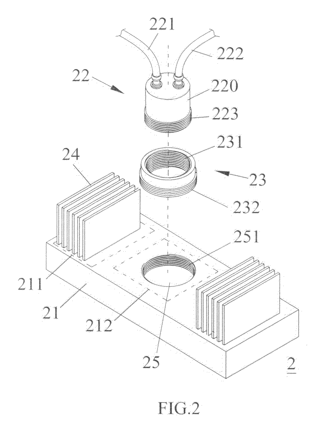
[0024]Referring to FIG. 2 and FIG. 3 for a three dimensional exploded diagram and an assembling side view of a liquid cooling heat dissipating device of first embodiment of the present invention, respectively, liquid cooling heat dissipating device 2 further comprises a base 21, a plurality of cooling fins 24, an adapter 23 and a liquid cooling module 22. One side of the base 21 is configured to contact with heat source in a thermally conductive manner, for example, the base 21 contacts with a surface of a chip via thermal grease. The surface of the other side of the base 21 has a first area 211 and a second area 212. The cooling fin 24 is disposed on the first area 211. Preferably, the cooling fin 24 and the base 21 are integrated conduction.
[0025]The second area 212 has an accommodating tank 25, in the inner wall of which has a thread 251. The outer wall of the adapter 23 has a thread 232 which is matched with the thread 251. Besides, the adapter 23 has an opening 25, and the inne...
second embodiment
[0033]FIG. 4 and FIG. 5 illustrate a three dimensional exploded diagram and an assembling side view of second embodiment of the liquid cooling heat dissipating device of the present invention respectively. The differences between the liquid cooling heat dissipating device 3 and liquid cooling heat dissipating device 2 are that the adapter 33 has a wedge 331, and one side of the liquid cooling module 32 has a protruded edge 323 which is matched with the wedge 331.
[0034]While assembling, the user can lock the adapter 33 on the accommodating tank 25 first, and then push the wedge 331 aside, and dispose the protruded edge 323 of the liquid cooling module 32 into the space surrounded by the wedge 331, and then release the wedge 331. The wedge 331 leans tightly against the body 220 due to the flexibility of the material of the wedge 331, and wedges the protruded edge 323 to fix the liquid cooling module 32, as shown in FIG. 5. By This way, the heat energy generated by the heat source can ...
third embodiment
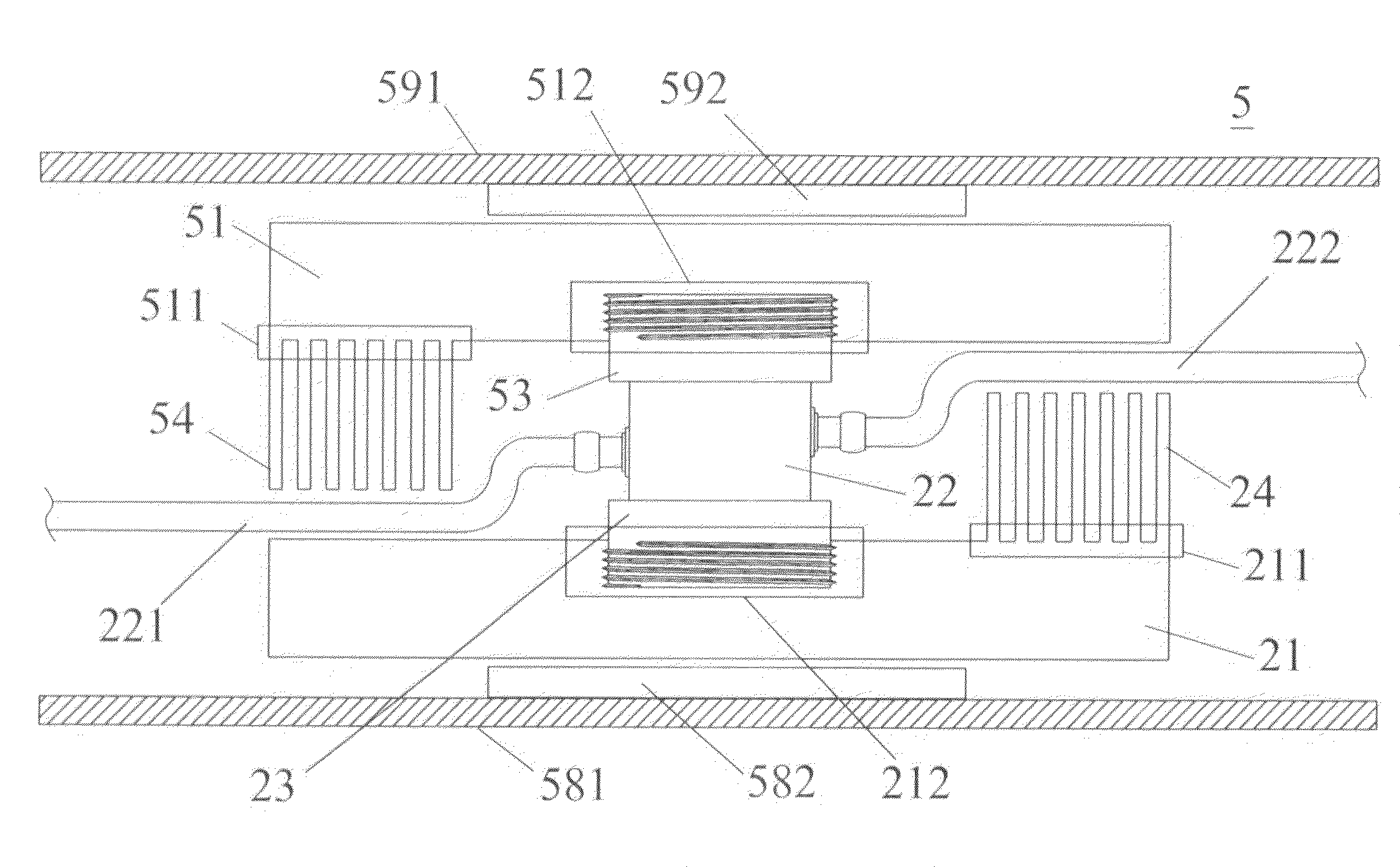
[0035]FIG. 6 illustrates an assembling side view of third embodiment of the liquid cooling heat dissipating device of the present invention. When heat dissipation for a plurality of heat source is required, a larger base can be used. One side of a base 41 of liquid cooling heat dissipating device 4 covers chips 491˜495, and the other side of the base 41 has a cooling fin 24 and a liquid cooling module 22. The users can remove the liquid cooling module 22 or install the liquid cooling module 22 on the base 41 according to their demand. The liquid cooling heat dissipating device 4 can be fixed on a circuit board 496 by using screw or tenon. For example, when a processing chip and a graphic chip are installed on main board, the liquid cooling heat dissipating device 4 of the present invention can used to dissipate the heat generated by the processing chip and the graphic chip. By using the liquid cooling heat dissipating device of the present invention and selecting the liquid cooling ...
PUM
 Abstract
Description
Claims
Application Information
 - R&D
- Intellectual Property
- Life Sciences
- Materials
- Tech Scout
- Unparalleled Data Quality
- Higher Quality Content
- 60% Fewer Hallucinations
Browse by: Latest US Patents, China's latest patents, Technical Efficacy Thesaurus, Application Domain, Technology Topic, Popular Technical Reports.
© 2025 PatSnap. All rights reserved.Legal|Privacy policy|Modern Slavery Act Transparency Statement|Sitemap|About US| Contact US: help@patsnap.com