
Floor cleansing system and method for use thereof

Inactive Publication Date: 2009-10-29
KARMIE KENNETH ALAN +2
View PDF45 Cites 2 Cited by
  • Summary
  • Abstract
  • Description
  • Claims
  • Application Information

AI Technical Summary

Benefits of technology

[0007]The present invention in one preferred embodiment contemplates a waste removal system for removing waste materials, the waste removal system including a floor base for receiving the waste materials, a floor covering spaced above the floor base, the floor covering adapted to support a human being or an animal, and being at least in part perme

Problems solved by technology

Either way, however, waste materials (i.e., unwanted liquids and solids) received on the floor covering, depending on whether the floor covering is permeable, can pass therethrough, or remain on and possibly soak the floor covering.
If the waste materials pass through the floor covering, the waste materials then can remain on the base, or, when padding is used, can potentially be trapped between the base and the floor covering by remaining on and possibly soaking the padding.
Accordingly, it can be difficult to remove waste materials from conventional flooring.
When conventional flooring is used, for example, in animal enclosures, having the waste materials remain on or possibly soak the floor covering, remain on the base, or be trapped between the base and the floor covering can have deleterious consequences.
However, such a rinsing operation is time consuming to the user, requires removal of the animals therefrom, and necessitates wetting the entire floor.
Furthermore, if the waste materials are not removed from the floor, the waste materials may cause unhygienic conditions in the animal enclosures.

Method used


Image

  • Floor cleansing system and method for use thereof
  • Floor cleansing system and method for use thereof
  • Floor cleansing system and method for use thereof

Examples


Embodiment Construction

[0017]The following description is intended to be representative only and not limiting, and many variations can be anticipated according to these teachings. Reference will now be made in detail to the preferred embodiments of this invention, examples of which are illustrated in the accompanying drawings.

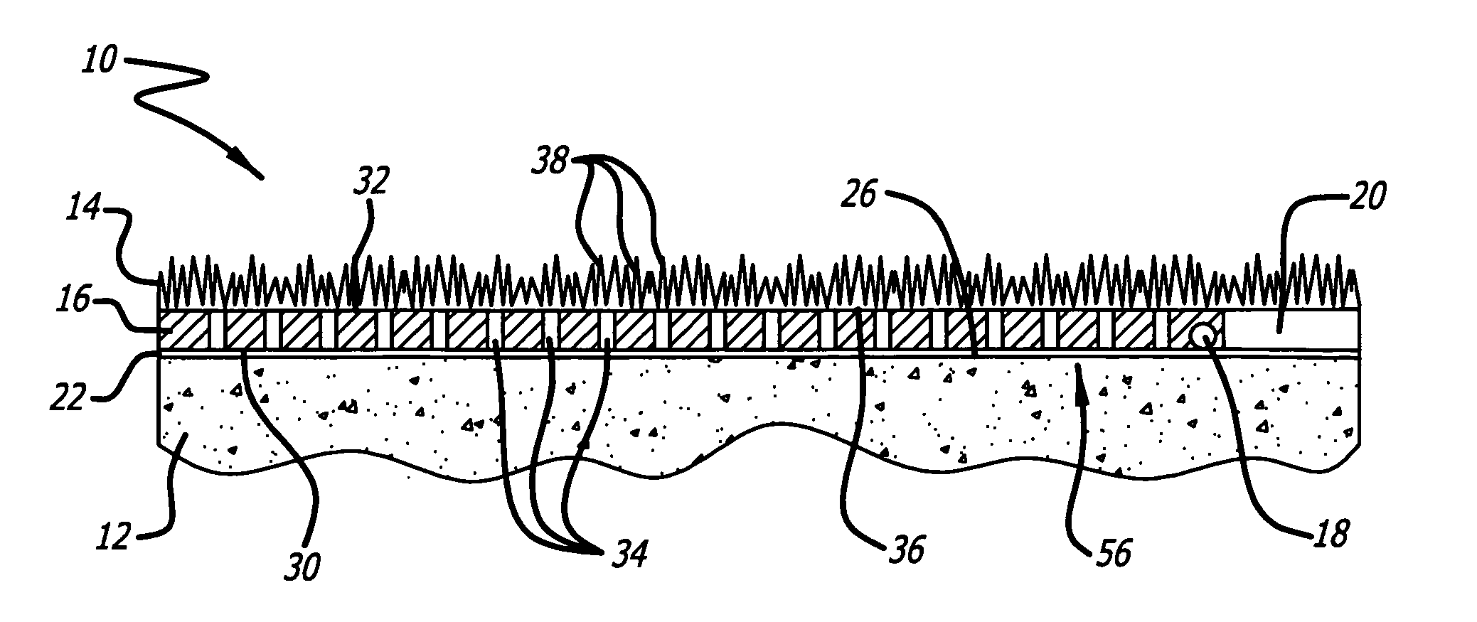
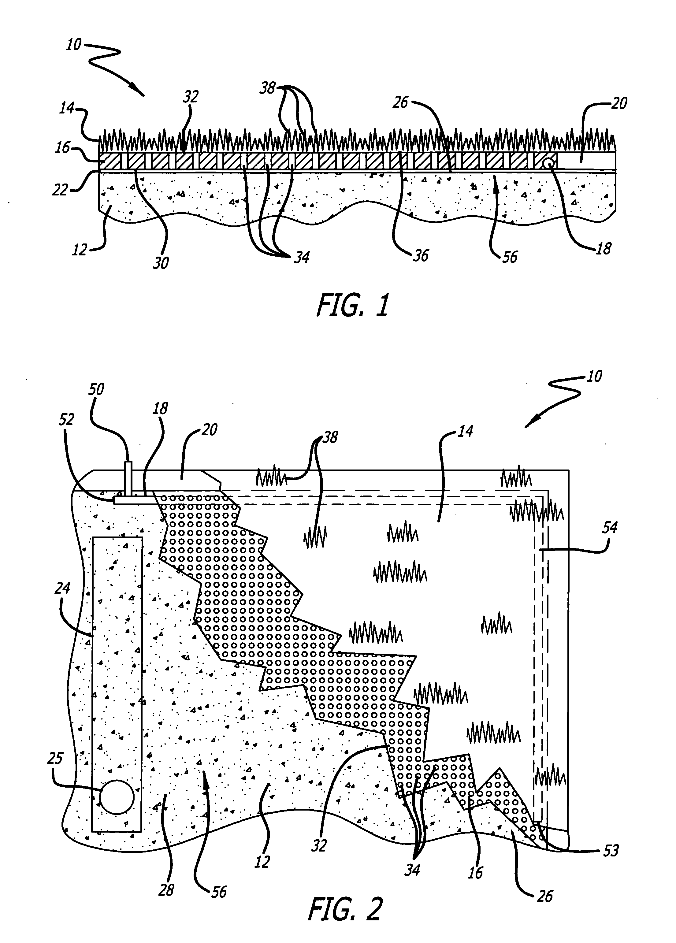
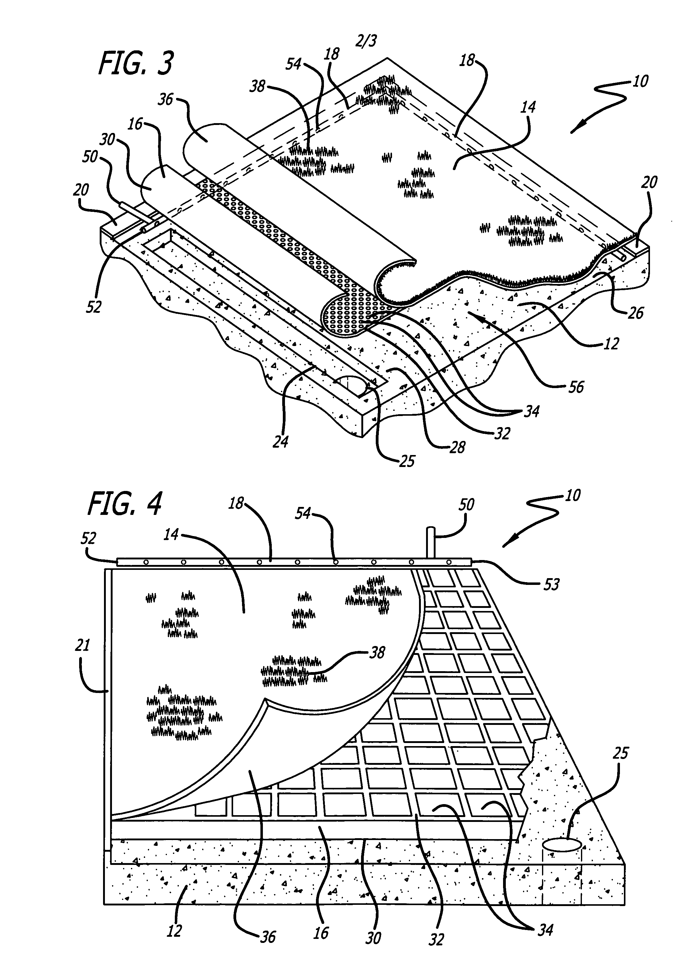
[0018]FIGS. 1-3 show one preferred embodiment and FIG. 4 shows another preferred embodiment of a waste removal system according to the present invention. In FIGS. 1-3 and FIG. 4, the preferred embodiments of the waste removal system are generally indicated by the numeral 10, and like numerals are used to indicate similar elements of the embodiments. Waste removal system 10 can serve as flooring for an area exposed to unwanted liquid and solid waste materials. Waste removal system 10 can be used in an indoor or an outdoor setting, and is provided to facilitate removal of the unwanted liquid and solid waste materials received thereon.

[0019]For example, waste removal system 10 can be us...


PUM


Abstract

A floor cleaning system and method for use thereof is disclosed for facilitating removal of waste materials. The system includes a floor base, a floor covering, a substrate spacing the floor base and the artificial grass surfacing apart from one another, and at least one fluid-carrying structure. The floor base receives the waste materials. The floor covering is spaced above the floor base, and is at least in part permeable to the waste materials and in liquid communication with the floor base. The fluid-carrying structure is adapted to provide cleaning fluid to the floor base to rinse the waste materials received thereon. The cleaning fluid and waste materials flow along the floor base under the floor covering to facilitate evacuation thereof. The method includes supporting the floor covering spaced above the floor base; exposing the floor covering to the waste materials; passing the waste materials through the floor covering to the floor base; rinsing the waste materials from the floor base with a cleaning fluid; and draining the cleaning fluid and the waste materials from the floor base.

Description

BACKGROUND OF THE INVENTION[0001]1. Field of the Invention[0002]The present invention is generally related to a floor adapted to facilitate removal of waste materials therefrom. More particularly, the present invention is related to a floor having a floor base for receiving unwanted waste liquids and solids, a floor covering for passing the waste materials therethrough, and a built-in rinsing mechanism for facilitating removal of the waste materials from the floor base. More specifically, the present invention is related to a floor having a floor base for receiving waste liquids and solids thereon, a permeable floor covering for supporting human beings and animals and permitting passage of the waste materials therethrough, and a fluid-carrying structure for releasing cleaning fluids to rinse away and facilitate evacuation of the waste materials from the floor base.[0003]2. Description of the Prior Art[0004]Typically, conventional flooring can include a hard semi-impermeable base and...

Claims


Application Information

Patent Timeline
IPC IPC(8): A41G1/00B08B3/04
CPCB08B3/04E01C13/02A01K1/015E01C13/08E04B5/48E04F13/072
Inventor KARMIE, KENNETH ALANKARMIE, DALE EDWINKARMIE, BRIAN ANDREW
Owner KARMIE KENNETH ALAN
Learn More