Air pollutant control system and method for removing mercury in flue gas

Inactive Publication Date: 2009-10-29
MITSUBISHI HITACHIPOWER SYST LTD
View PDF2 Cites 2 Cited by
  • Summary
  • Abstract
  • Description
  • Claims
  • Application Information

AI Technical Summary

Benefits of technology

[0017]According to an aspect of the present invention, an air pollutant control system includes: a denitration apparatus that reduces nitrogen oxide in flue gas discharged from an industrial boiler, and that injects hydrogen chloride into the flue gas to oxidize mercury; a desulfurization apparatus that absorbs sulfur oxide in flue gas thus denitrated; a stack from which gas thus desulfurized is discharged outside; a hydrogen chloride vaporizer that produces hydrogen chloride with a supply of concentrated hydrochloric acid; and a hydrochloric acid neutralization tank where at least one of dilute hydrochloric acid discharged from the hydrogen chloride vaporizer and the concentrated hydrochloric acid is neutralized with an alkali agent. Chloride resulting from such neutralization is supplied to a fuel, and then burned in the industrial boiler to produce hydrogen chloride in flue gas, and, together with hydrogen chloride sprayed, the mercury is reduced.
[0018]According to another aspect of the present invention, an air pollutant control system includes: a spray device that sprays hydrogen chloride into flue gas discharged from a coal combustion boiler; a denitration apparatus that reduces nitrogen oxide in flue gas into which the hydrogen chloride has been sprayed, and that oxidizes mercury; an air heater that recovers heat in gas from which the nitrogen oxide has been reduced; a dust collector that reduces dust in gas from which the heat has been collected; a desulfurization apparatus that absorbs sulfur oxide in gas from which the dust has been reduced; a stack from which gas thus desulfurized is discharged outside; a hydrogen chloride vaporizer that produces hydrogen chloride with a supply of concentrated hydrochloric acid; and a hydrochloric acid neutralization tank where at least one of dilute hydrochloric acid discharged from the hydrogen chloride vaporizer and the concentrated hydrochloric acid is neutralized with an alkali agent. Neutralized chloride is supplied to a coal feeder, mixed with coal, and then burned in the coal combustion boiler, so as to produce hydrogen chloride in flue gas, and, together with hydrogen chloride sprayed, the mercury is reduced.

Problems solved by technology

These methods, however, require special means for absorption removal, and are not suitable for treatment of a large volume of flue gas, such as flue gas in power stations.
This poses a problem that the dilute hydrochloric acid results in a waste product for the power station.
This increases costs for establishing and maintaining the plants.
In addition, the mercury concentration in flue gas is not constant all the time.
This poses a problem that hydrogen chloride cannot be supplied by a constant amount so that mercury is securely reduced as mercury chloride.

Method used


Image

  • Air pollutant control system and method for removing mercury in flue gas
  • Air pollutant control system and method for removing mercury in flue gas
  • Air pollutant control system and method for removing mercury in flue gas

Examples


first embodiment

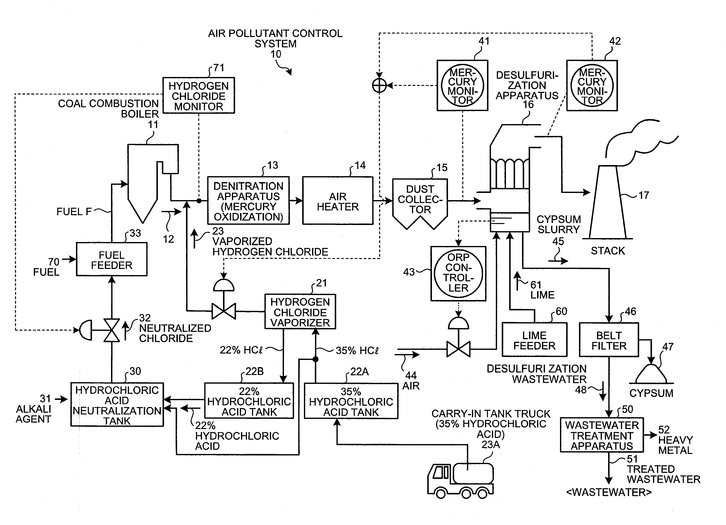
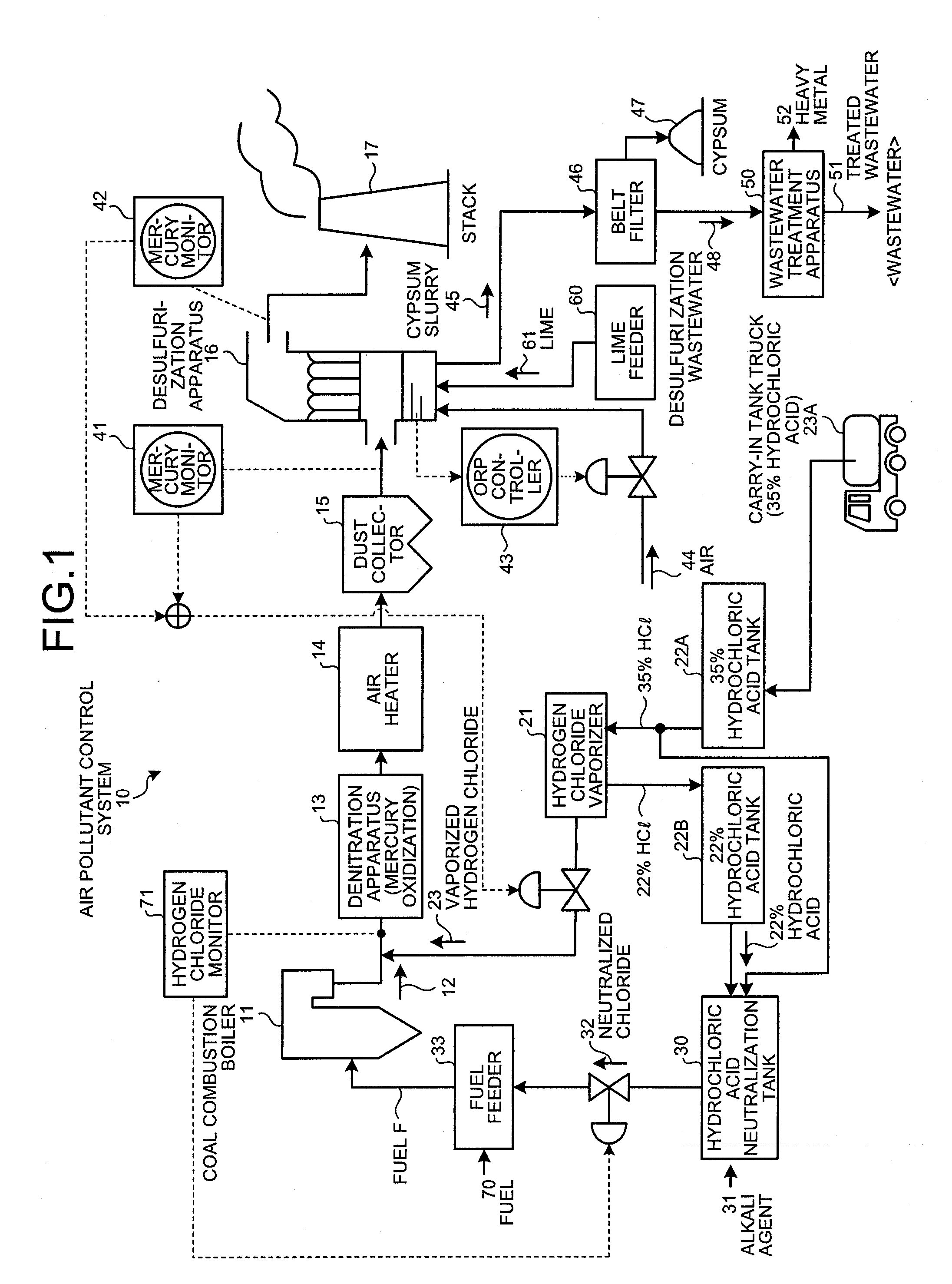
[0032]FIG. 1 is a schematic diagram of an air pollutant control system according to a first embodiment. As shown in FIG. 1, an air pollutant control system 10 according to the present embodiment includes: the denitration apparatus 13 that reduces nitrogen oxide in flue gas 12 discharged from the coal combustion boiler 11, and that sprays hydrogen chloride 23 into the gas to oxidize mercury; the air heater 14 that recovers heat in gas from which the nitrogen oxide has been reduced; the dust collector 15 that reduces dust in gas from which the heat has been collected; the desulfurization apparatus 16 that reduces sulfur oxide in gas from which the dust has been reduced; the stack 17 from which desulfurized gas is discharged to the outside; the hydrogen chloride vaporizer 21 that evaporates concentrated hydrochloric acid (35% HCl) to produce hydrogen chloride 23; and a hydrochloric acid neutralization tank 30 where dilute hydrochloric acid (22% HCl) discharged from the hydrogen chlorid...

second embodiment

[0052]In the air pollutant control system 10B shown in FIG. 3, a portion 48B of the desulfurization wastewater 48, discharged from the desulfurization apparatus 16, is supplied to the hydrochloric acid neutralization tank 30. Then, by diluting the aqueous chloride solution and combustion it in the boiler, it is possible to significantly reduce the amount of treated wastewater to be discharged to the outside.

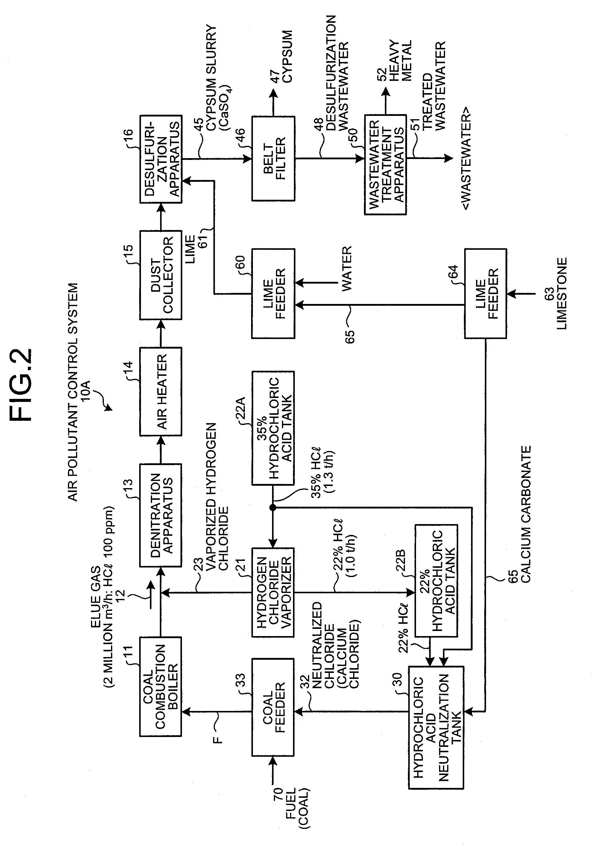
[0053]In the desulfurization wastewater 48, calcium chloride produced by a limestone / gypsum process is present in an aqueous solution (about 20000 ppm). By supplying it to the hydrochloric acid neutralization tank 30, the chloride concentration can be increased. This makes it possible to reduce the amount of concentrated hydrochloric acid to be supplied to 1.0 tons per hour, which is about 20% reduction. The diluted amount is set so as not to affect the boiler operation, and about 55% to 60% may be used as dilution water.

[0054]Instead of the desulfurization wastewater 48, a treat...


PUM

PropertyMeasurementUnit
Fractionaaaaaaaaaa
Concentrationaaaaaaaaaa

Abstract

An air pollutant control system comprises: a denitration apparatus that reduces nitrogen oxide in flue gas discharged from a coal combustion boiler, and that sprays hydrogen chloride into the gas to oxidize mercury, an air heater that recovers heat in gas, a dust collector that reduces dust in gas, a desulfurization apparatus that reduces sulfur oxide in gas from which the dust has been reduced, a hydrogen chloride vaporizer that evaporates concentrated hydrochloric acid to obtain the hydrogen chloride, and a hydrochloric acid neutralization tank where dilute hydrochloric acid discharged from the hydrogen chloride vaporizer or the concentrated hydrochloric acid is neutralized with an alkali agent. Neutralized chloride is supplied to a fuel feeder, mixed with a fuel, and then burned as a fuel in a boiler to produce hydrogen chloride in flue gas. Together with sprayed hydrogen chloride derived from the hydrogen chloride vaporizer, the mercury is reduced.

Description

BACKGROUND OF THE INVENTION[0001]1. Field of the Invention[0002]The present invention relates to a flue gas treatment system that reduces mercury in flue gas discharged from a boiler, and to a method for removing mercury in flue gas.[0003]2. Description of the Related Art[0004]Conventionally, various systems for removing mercury in flue gas have been considered because, for example, coal combustion boilers serving as combustion apparatuses in power stations and other facilities discharge flue gas containing highly toxic mercury.[0005]A coal combustion boiler generally includes a wet desulfurization apparatus for removing sulfur content in flue gas. In flue gas treatment facilities including such a boiler provided with a desulfurization apparatus that serves a flue gas treatment apparatus, as chlorine (Cl) content increases in flue gas, the ratio of water-soluble divalent metallic mercury increases. This facilitates collection of the mercury with the desulfurization apparatus, as is ...

Claims


Application Information

Patent Timeline
IPC IPC(8): B01D53/46B01J19/00
CPCB01D53/501B01D53/508B01D53/56B01D53/64B01D53/75B01D2251/404F23J2215/60B01D2251/606B01D2257/602F23J7/00F23J15/003F23J15/006B01D2251/502B01D53/8625B01D53/8665B01D53/90Y02A50/20
Inventor MURAKAMI, MORITOSHIUKAI, NOBUYUKINAGAYASU, TATSUTO
Owner MITSUBISHI HITACHIPOWER SYST LTD
Why Eureka
Try Eureka