Microwave Generating Apparatus and Microwave Generating Method
a technology of generating apparatus and microwave, which is applied in the direction of pulse generator, electric/magnetic/electromagnetic heating, pulse technique, etc., can solve the problems of increasing the cost of the apparatus, affecting the operation efficiency of the respective semiconductor device, and reducing the efficiency of the respective operation. , the effect of reducing the cost and improving the efficiency of the operation
- Summary
- Abstract
- Description
- Claims
- Application Information
AI Technical Summary
Benefits of technology
Problems solved by technology
Method used
Image

Examples
first embodiment
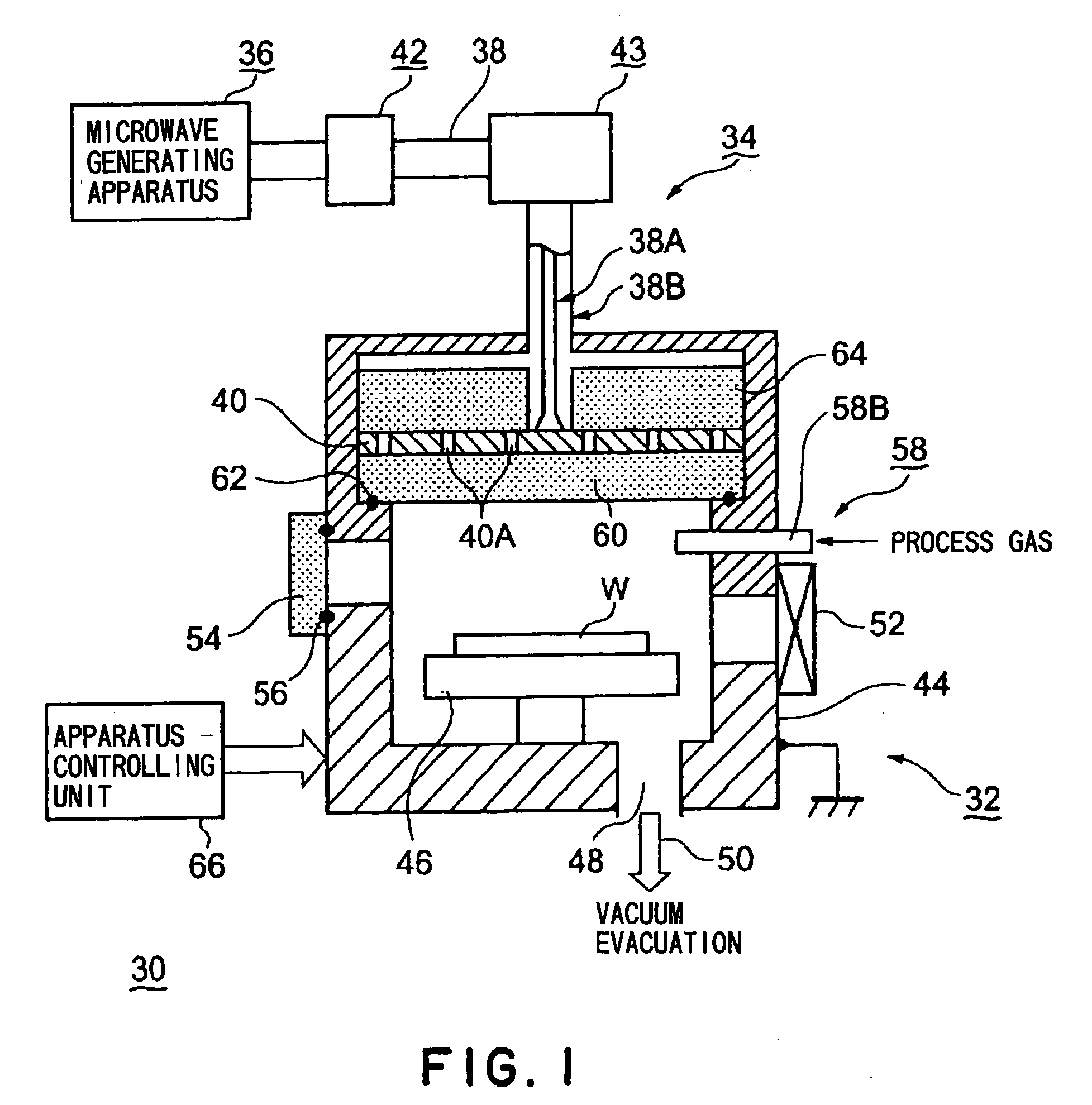
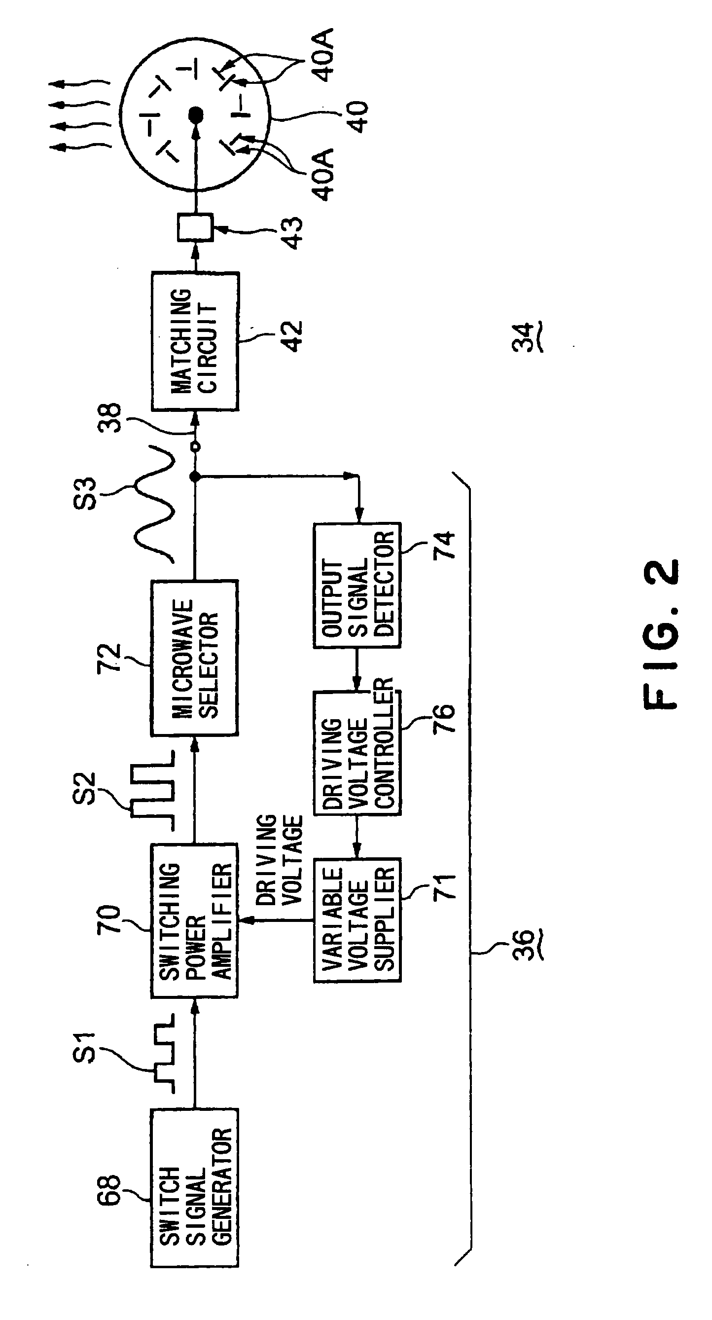
[0033]FIG. 1 is a schematic structural view of a plasma processing apparatus in one embodiment using a microwave generating apparatus according to the present invention. FIG. 2 is a block diagram of a microwave generating apparatus (and a microwave supplying apparatus) in a first embodiment of the present invention. FIG. 3 is a circuit principle view of (an example of) a main part of the microwave generating apparatus shown in FIG. 2.
[0034]As shown in FIG. 1, a plasma processing apparatus 30 is mainly composed of an apparatus body 32 in which a plasma process is actually performed, and a microwave supplying apparatus 34 for supplying a microwave into the apparatus body 32.
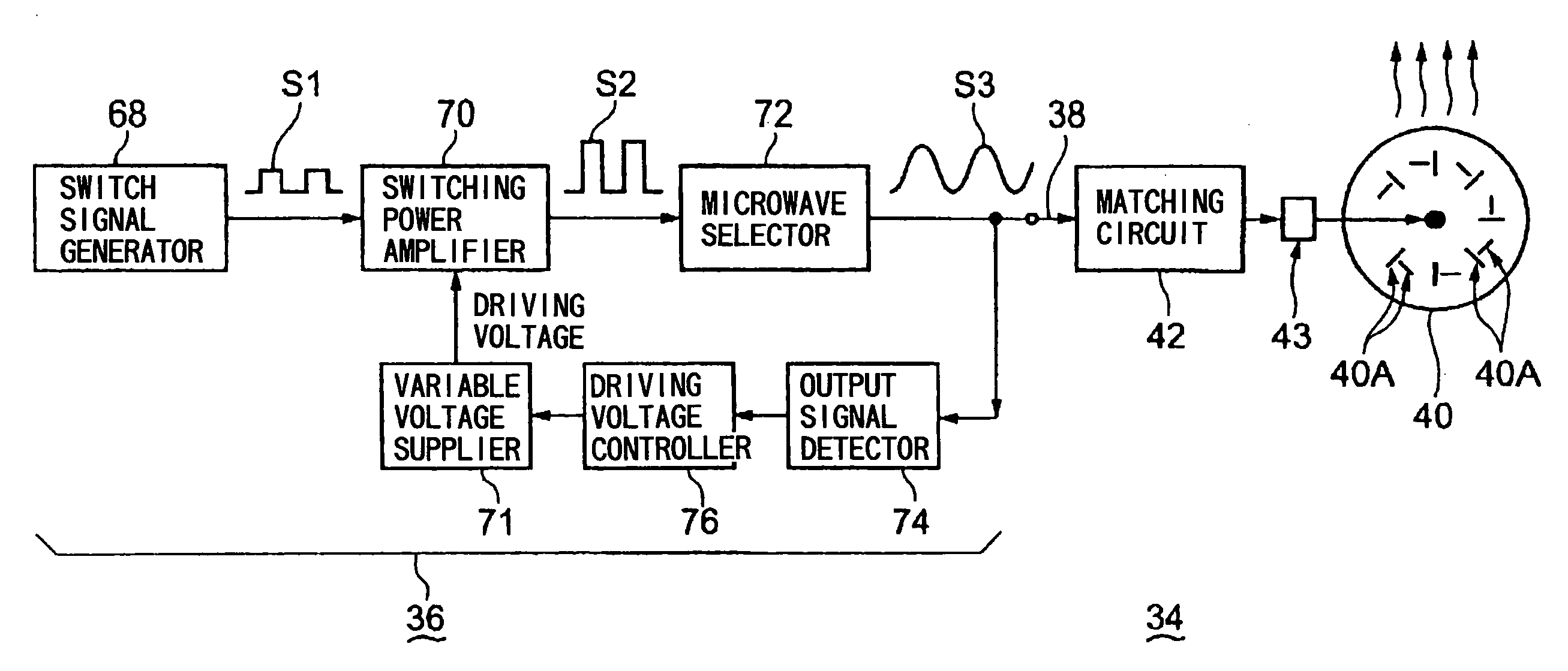
[0035]As shown in FIGS. 1 and 2, the microwave supplying apparatus 34 is mainly composed of: a microwave generating apparatus 36; an antenna part 40 connected to the microwave generating apparatus 36 via a coaxial waveguide 38 as a transmission line; and a matching circuit 42 disposed at an intermediate position of...
second embodiment
[0060]In the first embodiment, the output signal detector 74 for detecting an output of the microwave selector 72 is disposed in order to obtain a feedback signal to be supplied to the driving voltage controller 76. However, in place of the output signal detector 74, there may be employed a light detector that detects a light emitted from a plasma generated in the processing vessel 44. FIG. 5 is a block diagram of a microwave generating apparatus in a second embodiment adopting such a structure. In FIG. 5, the parts having the same structure as the parts shown in FIG. 2 are shown by the same reference numbers, and their detailed description is omitted.
[0061]As shown in FIG. 5, in this embodiment, in place of the output signal detector 74 shown in FIG. 2, there is disposed a light detector 82 that detects a light emitted from a plasma generated in a processing vessel 44. The light detector 82 generates a feedback signal. For example, by using an emission spectrometer as the light det...
third embodiment
[0062]In the first and second embodiments, the sine wave signal S3 output by the microwave selector 72 is supplied to the antenna part 40. However, it is possible to employ a structure in which provision of the microwave selector 72 is omitted, and an output of the switching power amplifier 70 is directly supplied to the antenna part 40. FIG. 6 is a block diagram of a microwave generator in a third embodiment adopting such a structure. In FIG. 6, the parts having the same structure as the parts shown in FIGS. 2 and 5 are shown by the same reference numbers, and their detailed description is omitted.
[0063]As shown in FIG. 6, in this embodiment, provision of the microwave selector 72 (see, FIG. 5) is omitted, and a square wave amplified signal S2, which is an output of an switching power amplifier 70 disposed on an upstream side of the microwave selector 72, is propagated to an antenna part 40 through a matching circuit 42 and a mode converter 43. In this case, the antenna part 40 is ...
PUM
 Abstract
Description
Claims
Application Information
 - R&D
- Intellectual Property
- Life Sciences
- Materials
- Tech Scout
- Unparalleled Data Quality
- Higher Quality Content
- 60% Fewer Hallucinations
Browse by: Latest US Patents, China's latest patents, Technical Efficacy Thesaurus, Application Domain, Technology Topic, Popular Technical Reports.
© 2025 PatSnap. All rights reserved.Legal|Privacy policy|Modern Slavery Act Transparency Statement|Sitemap|About US| Contact US: help@patsnap.com