
Hoisting device

a hoisting device and hoisting technology, applied in the direction of hoisting equipment, mechanical equipment, machines/engines, etc., can solve the problems of increasing the complexity and weight of the reel and the hoist in general, increasing the complexity and weight of the hoisting structure, and large hoisting size, etc., to achieve increased user-friendliness of the hoisting device, improved safety and efficiency, and quick operation

Active Publication Date: 2009-10-29
PP ENERGY APS
View PDF22 Cites 34 Cited by
  • Summary
  • Abstract
  • Description
  • Claims
  • Application Information

AI Technical Summary

Benefits of technology

[0009]Hereby it is achieved that the hoisting device can be provided in a compact form, compared with traditionally used hoisting means, since the synthetic rope used as a hoisting line is characterized in having a high tensile strength and a low weight, whereby a rope having a comparable low weight can be used for lifting the same load, for which traditionally a steel wire having a relatively large weight has been used. Further, since the weight of the rope itself is relatively small, a drive motor, gear, etc. having reduced capacity, power etc., can be used as compared to a traditional hoist, thereby also aiding in reducing the size, weight, complexity, cost etc. of the hoisting device.
[0037]Preferably, as specified in claim 18, said one or more marking means may comprise a metal part, e.g. a metal wire or foil or another suitable part that is detectable by said sensor means in a contactless manner. Hereby, the end stop and / or the speed control functionality can be achieved in a relatively simple, flexible and efficient manner.

Problems solved by technology

Thus, such winches or hoists tend to be heavy and voluminous, not only because they have to accommodate a considerable length of e.g. steel wire, but also because steel wire has a relatively large weight, whereby the reel has to be designed for handling such a relatively large weight, thereby also adding to the complexity and weight of the reel and the hoist in general.
All in all, when using prior art hoists or winches equipped with steel wire in connection with e.g. wind turbines, a relatively large, heavy and complex hoisting structure has to be used, since the hoist in general has to be designed in order to cope with the relatively large weight.
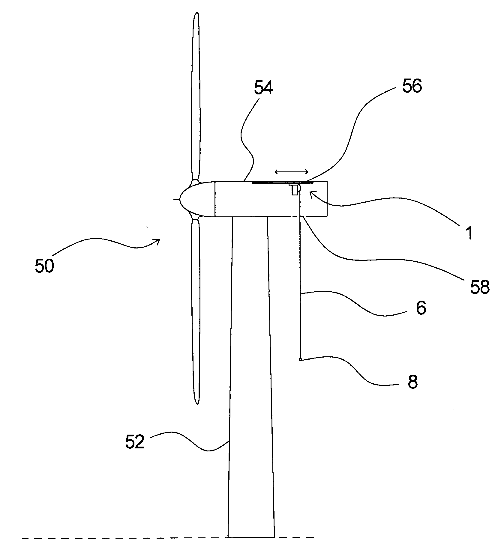
This gives rise to problems as regards for example the available space, for example when the nacelle of a wind turbine is concerned, where evidently a hoist can not be allowed to take up more space than absolutely necessary.

Method used


Image

  • Hoisting device
  • Hoisting device
  • Hoisting device

Examples


Embodiment Construction

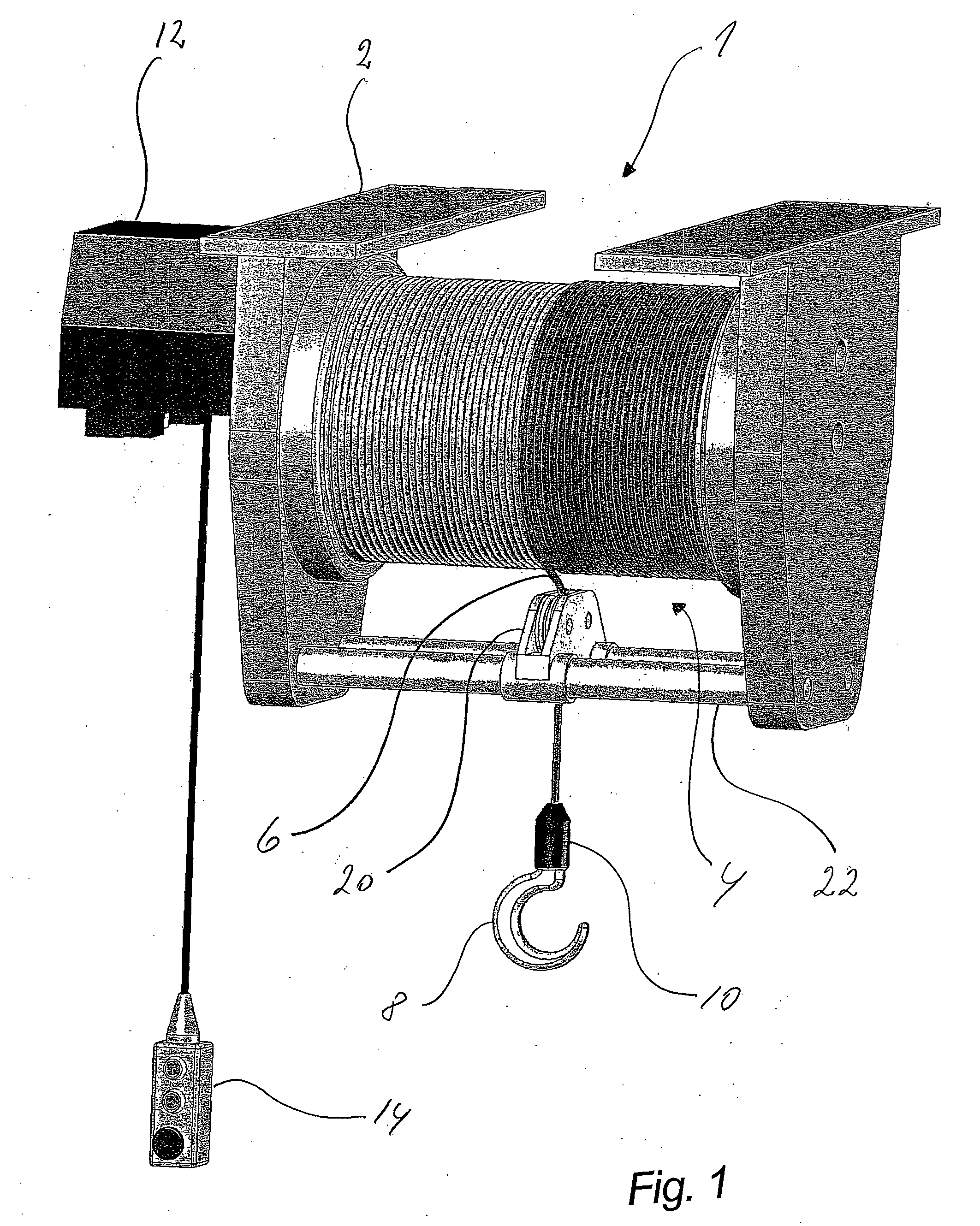
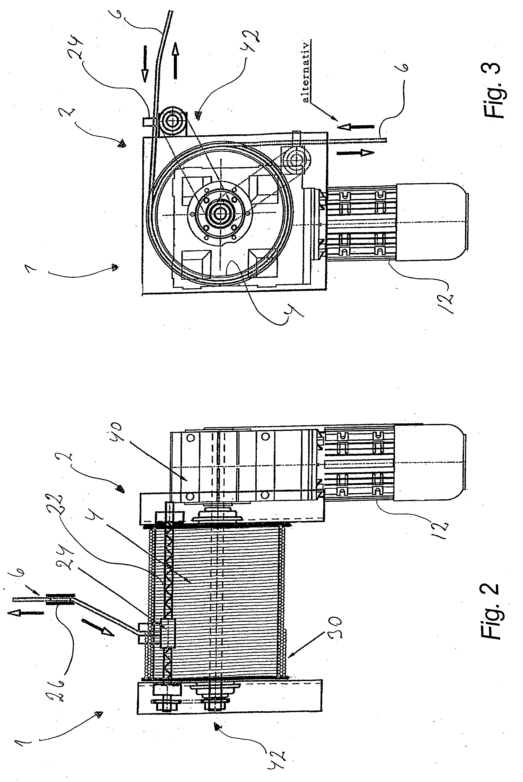
[0051]A hoisting device 1 is shown in FIG. 1 in a general manner, showing a frame 2 adapted for mounting the device to for example a crane trolley or the like, by means of which the device 1 can be moved. The frame 2 carries a reel or drum 4, which can be driven by means of a drive motor 12, and which accommodates the hoisting line 6, which shall be described in further detail below. The manner, in which the line is accommodated on the reel 4 shall also be further described in the following.

[0052]The hoisting line 6 is equipped with means such as e.g. a hook 8 for attaching an item to the line. As shown, connecting means 10 may be used for connecting the hook 8 to the line 6. The hoisting line 6 is wound on the reel 4 in one or more layers in such a manner that the line 6 is arranged in turns next to each other, guided by a line guiding arrangement 20, that is arranged for moving forth and back along e.g. traversing means 22.

[0053]Furthermore, means 14 for controlling the hoisting d...


PUM


Abstract

The invention relates to a hoisting device for use at a wind turbine, in particular for use in a wind turbine nacelle, which hoisting device includes a reel, a drive motor, control mean and a hoisting line. The hoisting line is a rope, which is composed of synthetic fibre material, e.g. a high-tech rope. Hereby it is achieved that the hoisting device can be provided in a compact form, compared with traditionally used hoisting means, since the synthetic rope used as a hoisting line is characterized in having a high tensile strength and a low weight, whereby a rope having a comparable low weight can be used for lifting the same load, for which traditionally a steel wire having a relatively large weight has been used. Further, since the weight of the rope itself is relatively small, a drive motor, gear etc. having reduced capacity, power etc., can be used as compared to a traditional hoist, thereby also aiding in reducing the size, weight, complexity, cost etc. of the hoisting device.

Description

FIELD OF THE INVENTION[0001]The invention relates to a hoisting device for use at a wind turbine, in particular for use in a wind turbine nacelle, which hoisting device comprises in general a reel, drive means, e.g. a drive motor, control means and a hoisting line.[0002]Further, the invention relates to uses of such a hoisting device.BACKGROUND OF THE INVENTION[0003]In connection with wind turbines it is normal practice to have a winch or hoist placed in the nacelle, for example placed in an upper position and possibly in such a manner that it can be displaced in the longitudinal direction of the nacelle and possibly also laterally. By means of such a winch or hoist various items such as tools, service parts, spare parts etc. may be lifted from the ground or sea surface up into the nacelle, for example through an opening in the floor or the side of the nacelle. Similarly, such a winch or hoist may also be used for lowering items down from the nacelle.[0004]Such winches or hoists are...

Claims


Application Information

Patent Timeline
IPC IPC(8): B66D1/38
CPCB66D1/38B66D1/46B66D1/54B66D3/20Y02E10/728F03D1/003F05B2240/221Y02E10/726F03D1/001F03D13/10F03D80/50Y02E10/72
Inventor TEICHERT, PAULKIRST, RUDOLF F.
Owner PP ENERGY APS
Learn More