
Method & system for multi-modality imaging of sequentially obtained pseudo-steady state data

a multi-modality, pseudo-steady state technology, applied in the field of multi-modality imaging systems, protocols and methods, can solve the problems of high installation cost, limited flexibility of the imaging system, and inability to fully integrate the imaging system

Inactive Publication Date: 2009-10-22
UNIV ZURICH +1
View PDF11 Cites 78 Cited by
  • Summary
  • Abstract
  • Description
  • Claims
  • Application Information

AI Technical Summary

Problems solved by technology

However, partially and fully integrated imaging systems have certain limitations.
Also, in order to implement a partially or completely integrated combined system, each imaging modality has an associated cost that is quite substantial.
Thus, it is very costly to install a complete new system having two modalities that are partially or fully integrated with one another.
Further, certain types of integrated dual-modality systems are difficult to design for operation so close to one another.
For example, it is difficult to operate an ultrasound, X-ray, CT, PET or SPECT scanner in close proximity with an MR scanner given the magnetic fields introduced into the examination area surrounding the MR scanner.

Method used


Image

  • Method & system for multi-modality imaging of sequentially obtained pseudo-steady state data
  • Method & system for multi-modality imaging of sequentially obtained pseudo-steady state data
  • Method & system for multi-modality imaging of sequentially obtained pseudo-steady state data

Examples


Embodiment Construction

[0021]Certain terms and phrases used throughout the present application shall be interpreted consistent with the explanations set forth herein.

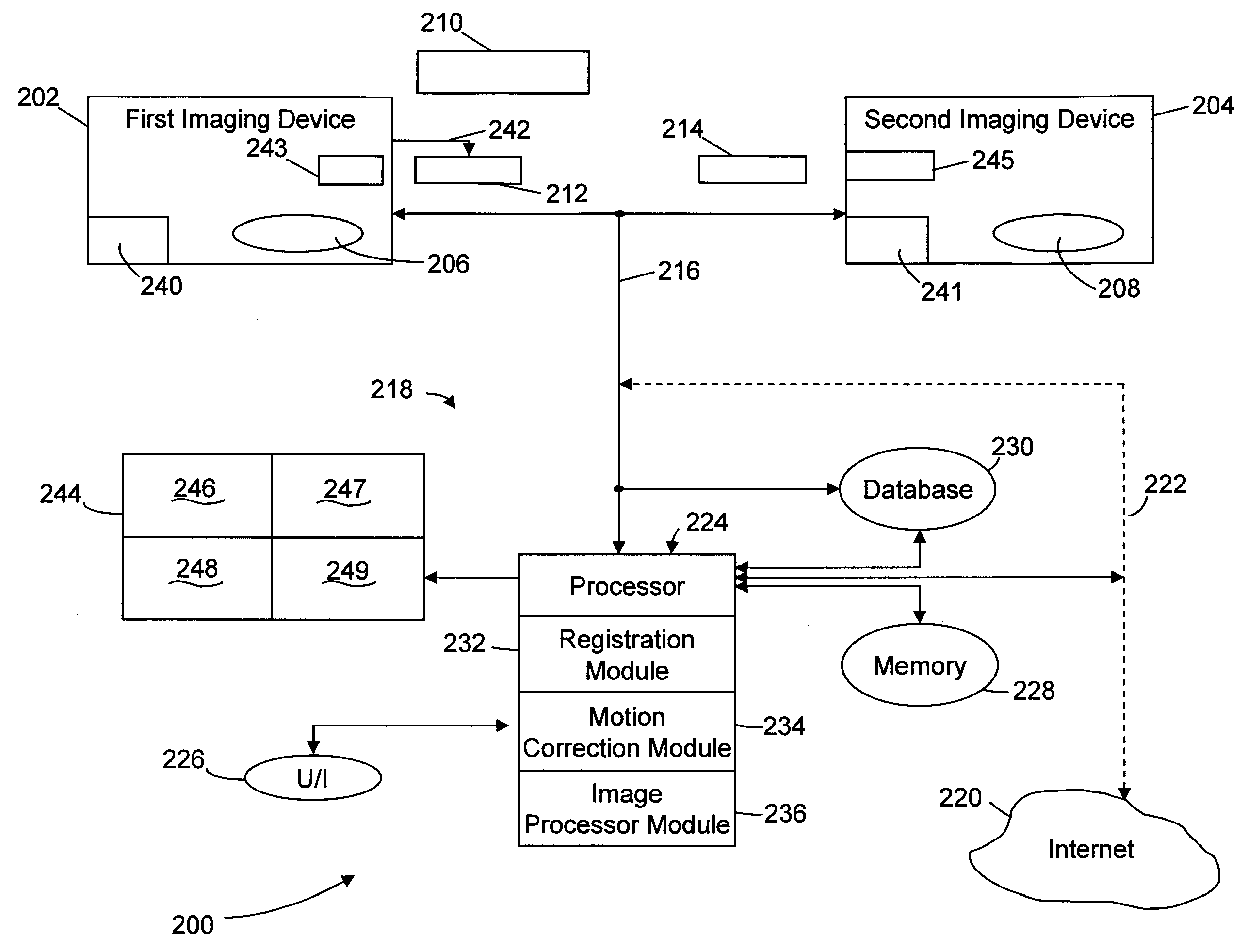
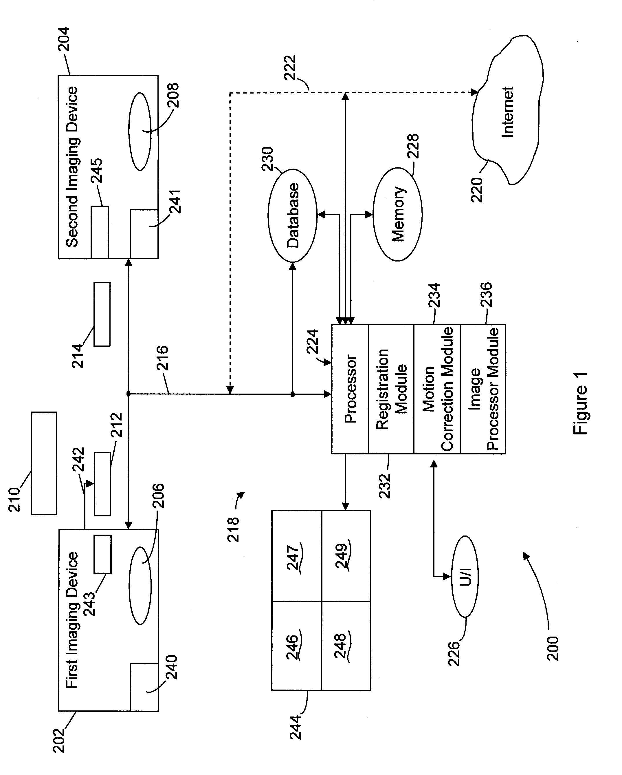
[0022]The term “physiologic structure,” as used throughout, shall include any structure within a human or animal, such as bone, vasculature, nerves, an organ, a group of organs, or a portion of an organ, or a tumor, as well as any system or portion of a system within a human or animal. By way of example only, the physiologic structure may include all or a portion of the heart, brain, blood-brain barrier, lungs, liver, kidneys, lymph nodes, thyroid, stomach, thorax, neck, intestines, colon and the like. As a further example, the physiologic structure may include the pulmonary system, the nervous system, the vascular system, the blood pool, the renal system, the digestive system and any other system within an animal or human. The term “region of interest” or “ROI.” as used throughout, shall include all or any portion of one or more physiologic ...


PUM


Abstract

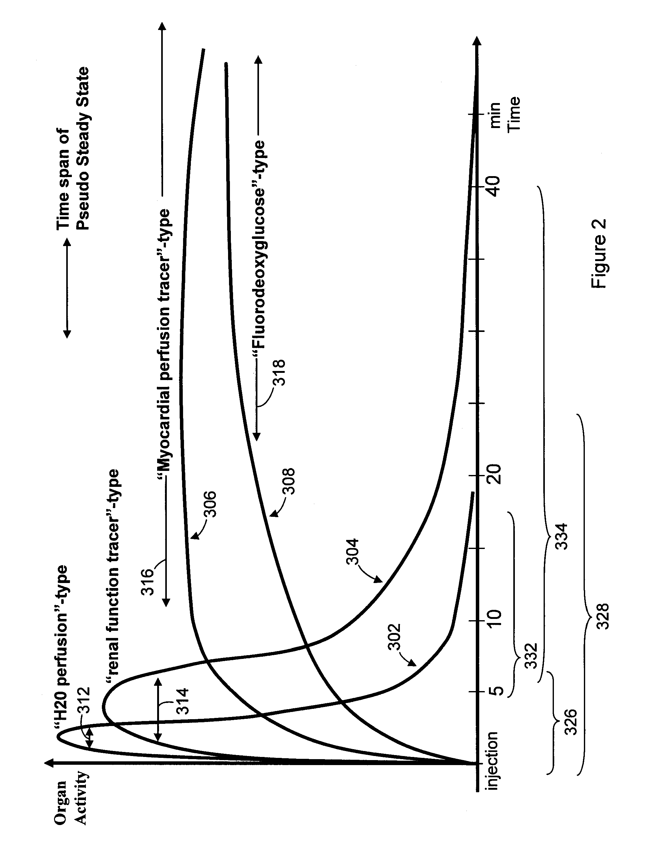
Methods, protocols and systems are provided for multi-modality imaging based on pharmacokinetics of an imaging agent. An imaging agent is introduced into a subject, and is permitted to collect generally in a region of interest (ROI) in the subject until attaining a pseudo-steady state (PSS) distribution within the ROI. The imaging agent records a first functional state of the ROI at a given point in time. A first image data set is obtained with a first imaging modality during a first acquisition time interval that occurs prior or proximate in time with the PSS time interval. The subject is transferred from the first imaging modality to a second imaging modality during a transfer time interval that overlaps the PSS time interval. Once transfer is complete, a second image data set is obtained with the second imaging modality during a second acquisition time interval that also overlaps the PSS time interval in which the imaging agent maintains the PSS distribution in the ROI. In accordance with a protocol, the transfer time interval and second acquisition time interval substantially fall within the PSS time interval. The imaging agent collects in the ROI during an uptake time interval which may or may not precede the time interval during which first imaging modality obtains at least a portion of the first image data set. The second image data set is obtained while the imaging agent persists in the ROI at the PSS distribution reflective of the first functional state even after the ROI is no longer in the first functional state.

Description

BACKGROUND OF THE INVENTION[0001]Embodiments of the present invention generally relate to systems, protocols and methods for multi-modality imaging that utilize imaging contrast agents or radiopharmaceutical agents to obtain image data sets.[0002]Today, a wide variety of imaging modalities exist for scanning various properties and characteristics of subjects. Examples of such imaging systems include positron emission tomography (PET), single photon emission computed tomography (SPECT), magnetic resonance imaging (MRI), computed tomography (CT), static X-ray imaging, dynamic X-ray imaging (fluoroscopy), ultrasound imaging, and optical imaging. Traditionally, the foregoing imaging systems were constructed and operated entirely separate and independent of one another. When operated independently, one imaging system would obtain one type of image data set representative of the subject at one point in time, while another imaging system would obtain another type of image data set represen...

Claims


Application Information

Patent Timeline
Patent Type & Authority Applications(United States)
IPC IPC(8): A61B5/00
CPCA61B5/0263A61B5/02755A61B5/055A61B5/201A61B5/415A61B8/5238A61B5/4244A61B6/032A61B6/037A61B6/5247A61B8/12A61B5/418
Inventor VON SCHULTHESS, GUSTAV K.SARAGNESE, EUGENE
Owner UNIV ZURICH
Learn More