
Pointer display device, pointer display/detection method, pointer display/detection program and information apparatus

a display device and display device technology, applied in the direction of instruments, computing, electric digital data processing, etc., can solve the problems of affecting and achieve the effect of reducing the convenience of use of the display devi

Active Publication Date: 2009-10-08
SONY CORP
View PDF5 Cites 106 Cited by
  • Summary
  • Abstract
  • Description
  • Claims
  • Application Information

AI Technical Summary

Benefits of technology

[0013]This ensures that a pointer can be displayed in the area containing the touch point upon a touch operation on the touch panel of the information apparatus, and a position corresponding to one part of the pointer exclusive of the touch point can be detected as the hotspot. Therefore, when a touch operation is conducted with a fingertip, for example, the hotspot can be detected through the one part of the pointer exclusive of the touch point of touch with the fingertip.
[0014]Thus, according to embodiments of the present invention, it is possible to display a pointer in an area containing a touch point in a touch operation on a touch panel, and to detect as a hotspot a position corresponding to one part of the pointer excluding the touch point. Therefore, when the touch operation is made with a fingertip, for example, the hotspot can be detected through the one part of the pointer exclusive of the touch point in the touch operation. Accordingly, it is possible to realize a pointer display device, a pointer display / detection method, a pointer display / detection program and an information apparatus in which a pointer facilitating user's input operations can be generated and displayed.

Problems solved by technology

In a display device with such a configuration, when the partition being selected with a fingertip is displayed as a magnified partition, the partitions located on the lower side of and adjacent to the magnified partition are hidden by the magnified partition so as to be invisible, which would naturally worsen the convenience in use of the display device.

Method used


Image

  • Pointer display device, pointer display/detection method, pointer display/detection program and information apparatus
  • Pointer display device, pointer display/detection method, pointer display/detection program and information apparatus
  • Pointer display device, pointer display/detection method, pointer display/detection program and information apparatus

Examples


Embodiment Construction

[0040]Now, an embodiment of the present invention will be described in detail below referring to the drawings.

(1) Structure of Mobile PC

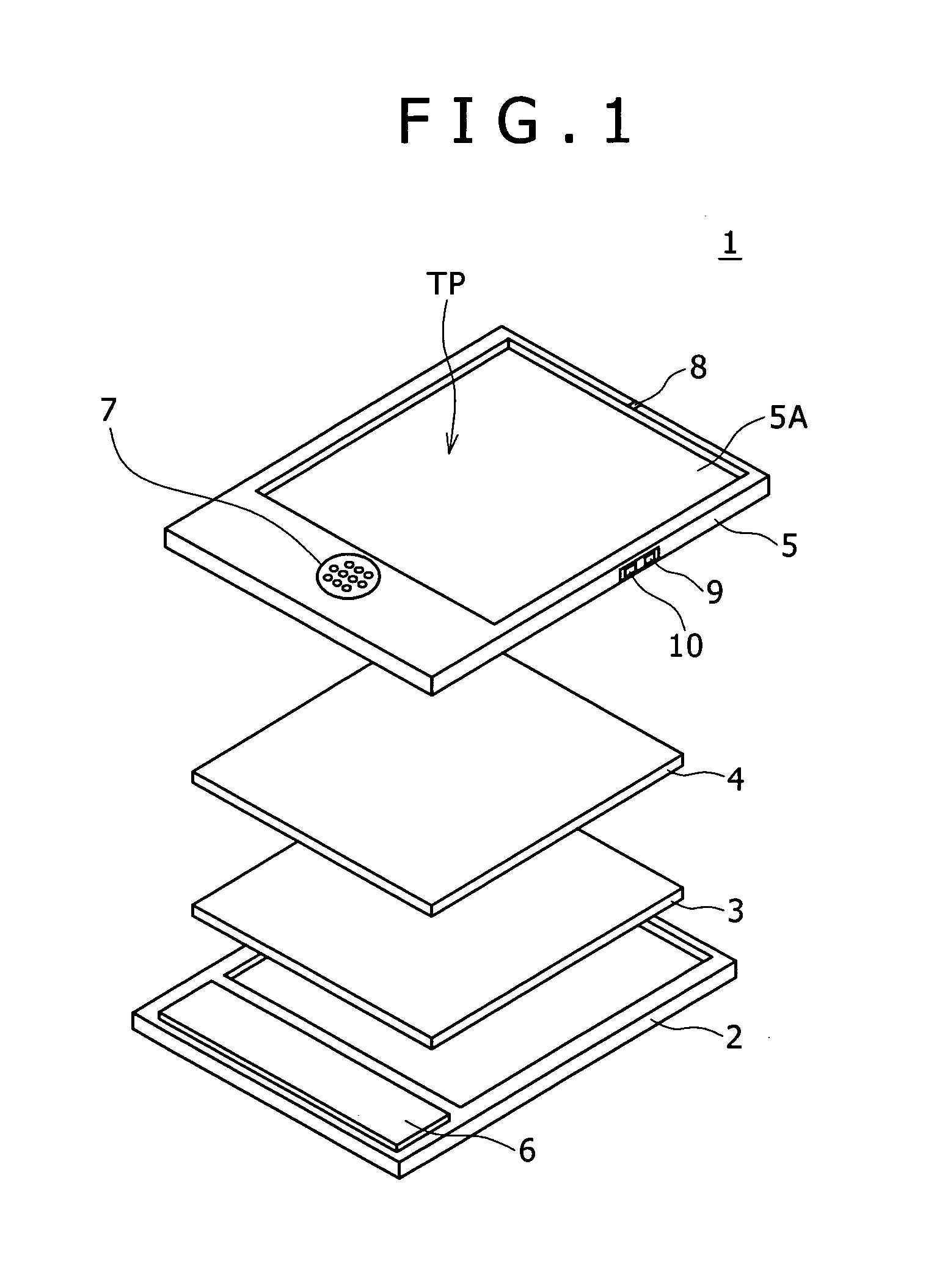
[0041]In FIG. 1, numeral 1 denotes a small mobile-type personal computer (hereinafter referred to as mobile PC) as an information apparatus according to an embodiment of the present invention, being substantially rectangular in overall shape and having reduced size and weight.

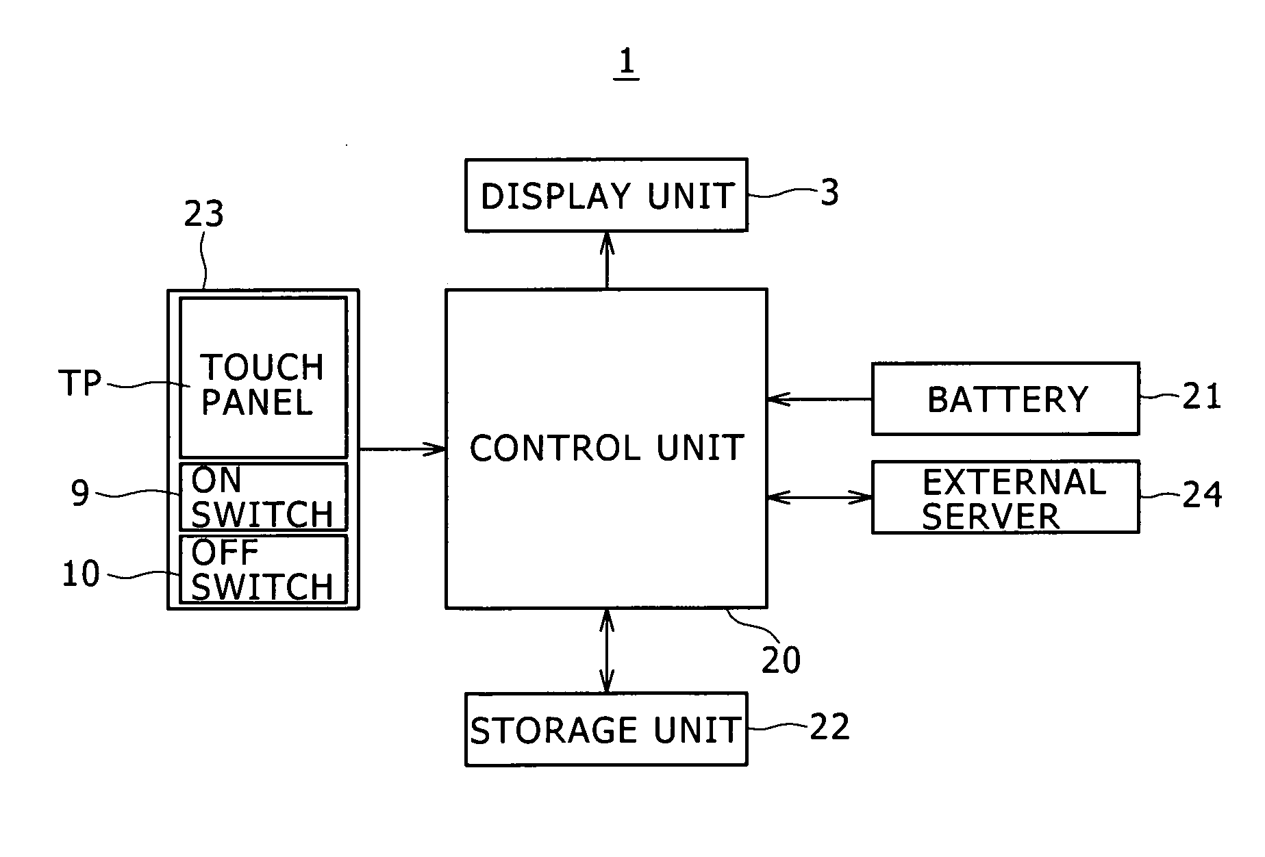
[0042]The mobile PC 1 has a body casing 2, a display unit 3 including, for example, a liquid crystal display, a touch sensor 4 and a cover casing 5, which are in a stacked state.

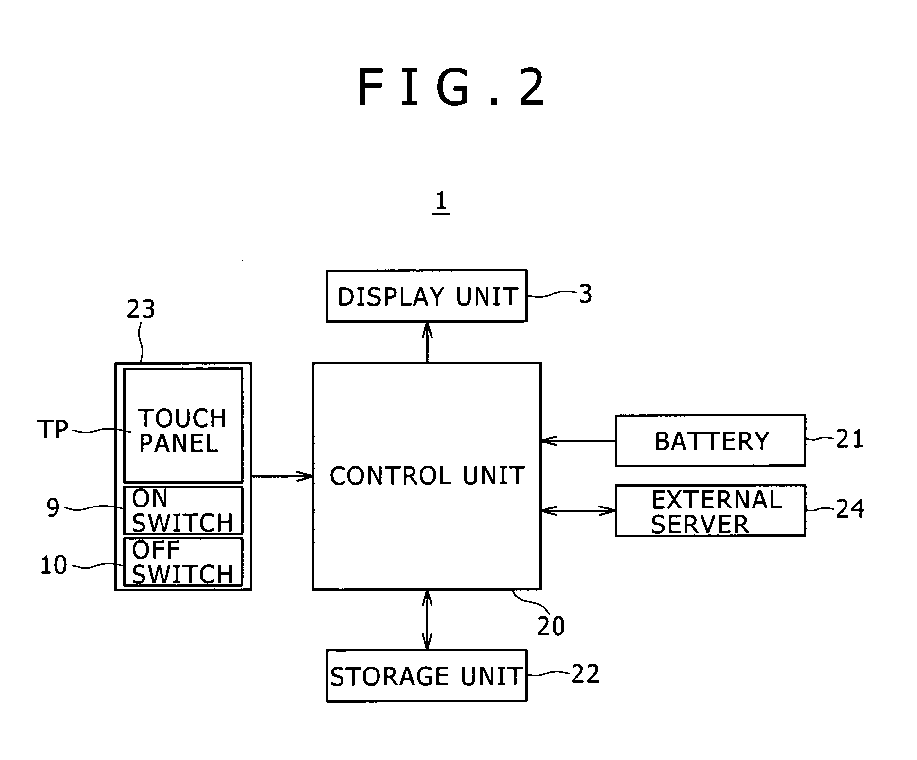
[0043]In practice, the mobile PC 1 has a structure in which an electronic circuit unit 6 including a control unit having a CPU (central processing unit), a storage unit having, for example, a semiconductor memory, and a battery and the like is contained in the body casing 2, and the display unit 3 is contained adjacently to the electronic circuit unit 6. In addition, onto a display surface of the displa...


PUM


Abstract

Disclosed herein is a pointer display device, including, a touch panel provided on a display screen of a display section, a pointer display section configured to detect a contact point in a touch operation on the touch panel and to display a pointer in an area containing the contact point, and a hotspot detection section configured to detect as a hotspot a position corresponding to one part of the pointer exclusive of the contact point.

Description

CROSS-REFERENCE TO RELATED APPLICATIONS[0001]The present application claims priority from Japanese Patent Application No. JP 2008-092059, filed in the Japanese Patent Office on Mar. 31, 2008, the entire content of which is incorporated herein by reference.BACKGROUND OF THE INVENTION[0002]1. Field of the Invention[0003]The present invention relates to a pointer display device, a pointer display / detection method, a pointer display / detection program and an information apparatus which are preferable for application to portable information apparatuses having a display unit provided with a touch panel, for example.[0004]2. Description of the Related Art[0005]In portable information apparatuses such as mobile PCs (personal computers), PDAs (personal digital assistants) and portable game machines, miniaturization of various devices has been progressing and miniaturization of the apparatuses themselves has also been made remarkably. Meanwhile, increases in the extents of complexity and versa...

Claims


Application Information

Patent Timeline
IPC IPC(8): G06F3/033G06F3/0481G06F3/0488
CPCG06F3/04812G06F3/0485G06F3/0412G06F3/041G06F3/0488G06F3/04817G06F3/0482
Inventor MORI, EIJIROIKEDA, TAKUOYANO, KEN
Owner SONY CORP
Learn More