
Beamforming weight determination method and device

A beamforming and determining method technology, applied in the field of communication, can solve problems such as system performance deterioration, achieve the effect of optimizing performance deterioration and improving system performance

Pending Publication Date: 2021-04-27
ZTE CORP
View PDF0 Cites 0 Cited by
  • Summary
  • Abstract
  • Description
  • Claims
  • Application Information

AI Technical Summary

Problems solved by technology

[0005] Embodiments of the present invention provide a method and device for determining beamforming weights, so as to at least solve the problem of relatively large system performance deterioration in related technologies

Method used


Image

  • Beamforming weight determination method and device
  • Beamforming weight determination method and device
  • Beamforming weight determination method and device

Examples


Embodiment 1

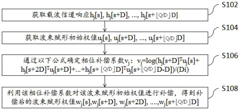
[0036] Embodiment 1 of the present invention provides a beamforming weight determination method, figure 1 is a flowchart of a beamforming weight determination method according to Embodiment 1 of the present invention, as shown in figure 1 As shown, the process includes the following steps:

[0037] Step S102, obtaining carrier channel response

[0038] Step S104, obtaining initial beamforming weights

[0039] Step S106, determine the phase compensation coefficient v by the following formula j :

[0040]

[0041] Step S108, using the phase compensation coefficient to compensate the beamforming initial weights to obtain the compensated beamforming weights

[0042] Wherein, j is the index of the user, and the carrier index occupied by user j is s, s+1, ..., s+Q, D is the sampling granularity, D is an integer greater than or equal to 1, Represents rounding down, log represents a logarithmic function based on a natural constant, T represents transpose, and i repres...


PUM


Abstract

The invention provides a beamforming weight determination method and device. According to a phase compensation coefficient determination method provided by the embodiment of the invention, after the beamforming weight is compensated, the problem of system performance deterioration caused by compensating the beamforming weight by adopting the phase compensation coefficient in the prior art can be optimized to a certain extent, and the effect of improving the system performance is achieved.

Description

technical field [0001] The present invention relates to the communication field, in particular to a method and device for determining a beamforming weight value. Background technique [0002] Beamforming is one of the key technologies in 4G systems and 5G systems. Commonly used beamforming algorithms include zero forcing (ZF) algorithm, minimum mean square error (minimal mean square error, MMSE) algorithm, matched filter (maximal ratio combine, MRC) algorithm, etc. The ZF algorithm sends user signals in the direction of the intended user and zero signals in the direction of other users. The MMSE algorithm maximizes the expected user signal-to-noise ratio. The MRC algorithm matches the filter of each signal to the channel. [0003] The ZF algorithm is generally used in the actual system, the input of the ZF algorithm is the channel response, and the output is the weight value. The ZF algorithm involves matrix inversion, and the computational complexity is very high. In o...

Claims


Application Information

Patent Timeline
Patent Type & Authority Applications(China)
IPC IPC(8): H04B7/06H04B7/08
CPCH04B7/0617H04B7/0682H04B7/0842
Inventor 吴昊李军
Owner ZTE CORP
Learn More