Projector and control method for projector
a projector and control method technology, applied in the direction of picture reproducers, picture reproducers using projection devices, instruments, etc., can solve the problems of reducing the convenience of the projector, requiring cooling of the light emitting tube portion, and the discharge lamp cannot be lighted, so as to minimize the deterioration of convenience and minimize the mercury bridge
- Summary
- Abstract
- Description
- Claims
- Application Information
AI Technical Summary
Benefits of technology
Problems solved by technology
Method used
Image
Examples
first embodiment
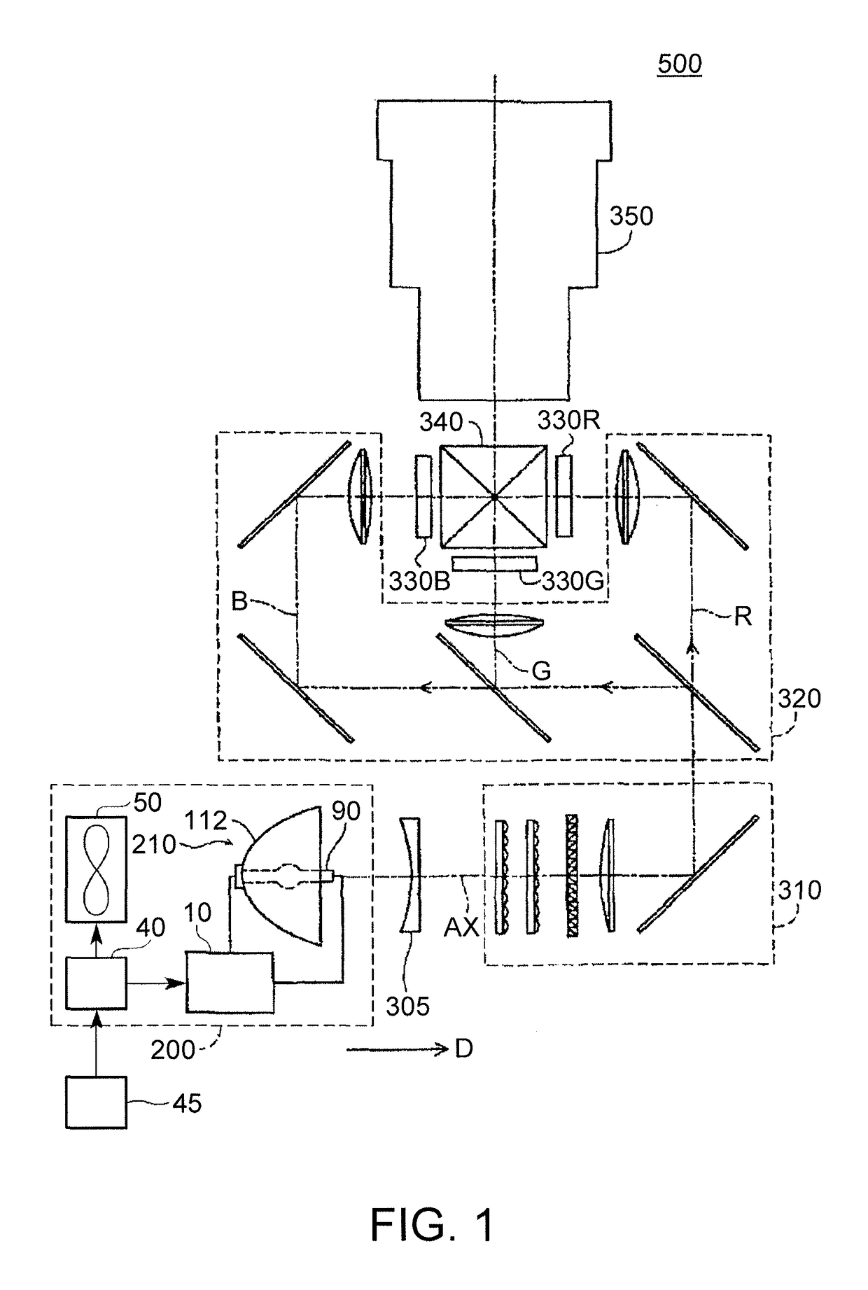
[0059]As illustrated in FIG. 1, a projector 500 of the present embodiment includes a light source apparatus 200, a collimating lens 305, an illumination optical system 310, a color separation optical system 320, three liquid crystal light valves (light modulation devices) 330R, 330G and 330B, a cross dichroic prism 340, and a projection optical system 350.
[0060]Light emitted from the light source apparatus 200 passes through the collimating lens 305 and is incident to the illumination optical system 310. The collimating lens 305 collimates the light from the light source apparatus 200.
[0061]The illumination optical system 310 adjusts the illuminance of the light emitted from the light source apparatus 200 so that the illuminance is uniformized on the liquid crystal light valves330R, 330G and 330B. The illumination optical system 310 aligns polarization directions of the light emitted from the light source apparatus 200 in one direction. This is aimed at effectively using the light e...
second embodiment
[0193]A second embodiment is different from the first embodiment in terms of a current waveform.
[0194]In the following description, the same constituent elements as in the first embodiment are given the same reference numerals, and description thereof will be omitted in some cases.
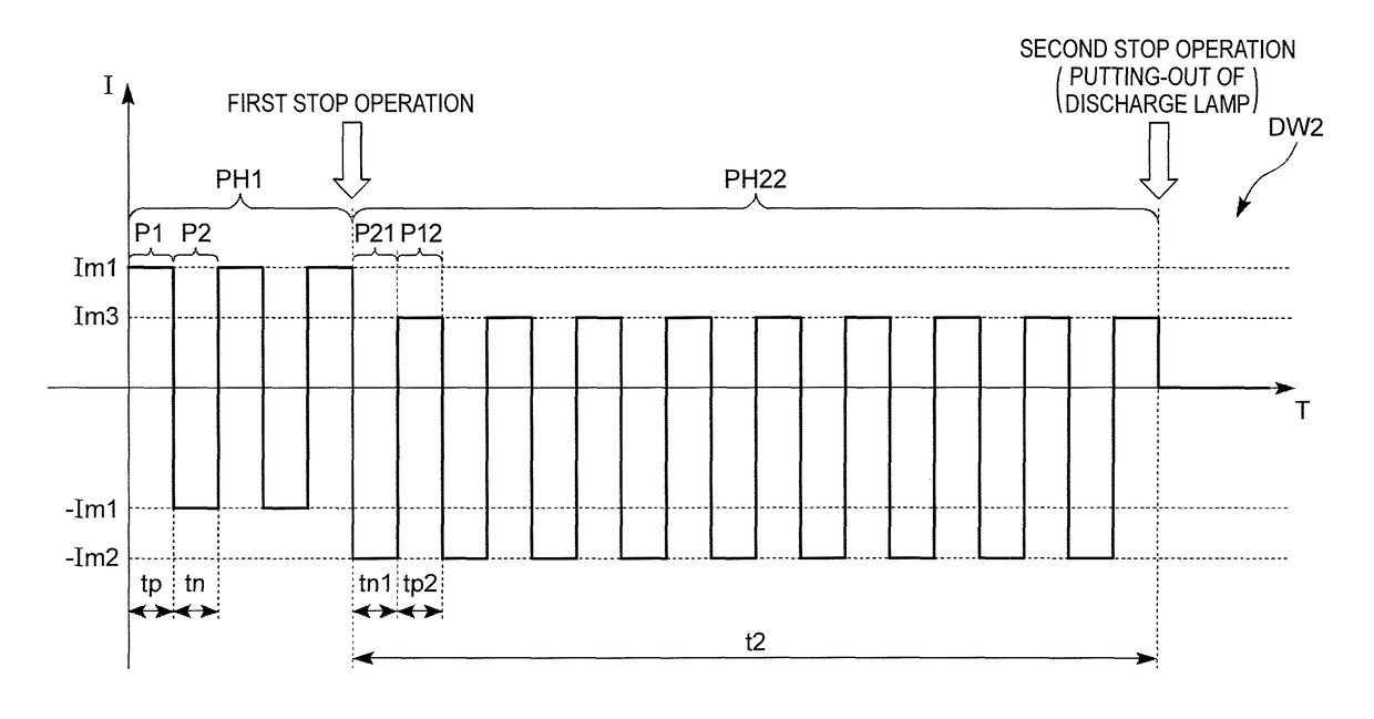
[0195]FIG. 10 is a diagram illustrating an example of a driving current waveform DW2 of the present embodiment. FIG. 10 illustrates the driving current waveform DW2 before and after the input reception unit 45 receives a stop operation.
[0196]As illustrated in FIG. 10, the driving current waveform DW2 (driving current I) includes the steady lighting period PH1 and a heating period (second AC period) PH22. In the present embodiment, the driving current waveform DW2 transitions from the steady lighting period PH1 to the heating period PH22 when the input reception unit 45 receives the first stop operation.
[0197]The heating period PH22 alternately includes a first polarity period P12 in which the first polarit...
third embodiment
[0208]A third embodiment is different from the first embodiment in that a length of a second polarity period is larger than a length of a first polarity period in a heating period. In the following description, the same constituent elements as in the first embodiment are given the same reference numerals, and description thereof will be omitted in some cases.
[0209]FIG. 11 is a diagram illustrating an example of a driving current waveform DW3 of the present embodiment. FIG. 11 illustrates the driving current waveform DW3 before and after the input reception unit 45 receives a stop operation.
[0210]As illustrated in FIG. 11, the driving current waveform DW3 includes the steady lighting period PH1 and a heating period PH23 in which an alternating current is supplied to the discharge lamp 90. In the present embodiment, the driving current waveform DW3 transitions from the steady lighting period PH1 to the heating period PH23 when the input reception unit 45 receives the first stop operat...
PUM
 Abstract
Description
Claims
Application Information
 - R&D
- Intellectual Property
- Life Sciences
- Materials
- Tech Scout
- Unparalleled Data Quality
- Higher Quality Content
- 60% Fewer Hallucinations
Browse by: Latest US Patents, China's latest patents, Technical Efficacy Thesaurus, Application Domain, Technology Topic, Popular Technical Reports.
© 2025 PatSnap. All rights reserved.Legal|Privacy policy|Modern Slavery Act Transparency Statement|Sitemap|About US| Contact US: help@patsnap.com


