
Screen manufacturing method and welding apparatus thereof

a screening screen and manufacturing method technology, applied in the direction of resistive welding apparatus, fluid removal, application, etc., can solve the problems of high factory cost of filter materials used in screening premiums, low productivity, and high cost of filter materials, so as to improve the welding quality of metal nets, reduce the number of leakage holes, and eliminate leakage phenomena

Inactive Publication Date: 2009-10-08
BEIJNG HINEN HITECH PETROLEUM TECH DEV
View PDF4 Cites 1 Cited by
  • Summary
  • Abstract
  • Description
  • Claims
  • Application Information

AI Technical Summary

Benefits of technology

This approach improves the welding quality of metal nets, increases the sand control capacity, and extends the lifespan of the screen, addressing the limitations of existing technologies by providing a cost-effective and reliable filtration solution.

Problems solved by technology

At present, most of filter materials used to make premium screen are very expensive multi-layer sintered metal net.
However, the filter material has high factory cost, low productivity and its size is limited by vacuum welding apparatus.
However, conventional welding technology has either low welding strength or leak phenomena (shrinkage hole phenomena) appears on welding parts of melt net.
However, the strength and reliability produced by these methods are relative low.
Although the screen may be made of non-sintered multi-layer composite net, during welding, shrinkage hole phenomena of multi-layer compound net is more serious than single-layer metal net.
At the same time, due to high thickness of screen and several-meter-long filter segment, series of difficulties are brought to welding procedure.
Thus how to obtain high quality and low cost screen welded by way of welding method from metal net is one big problem in the field.

Method used


Image

  • Screen manufacturing method and welding apparatus thereof
  • Screen manufacturing method and welding apparatus thereof
  • Screen manufacturing method and welding apparatus thereof

Examples


Embodiment Construction

[0027]The solution provided by the present invention will be better understood from following detailed description of preferred embodiments of the invention with reference to the drawings.

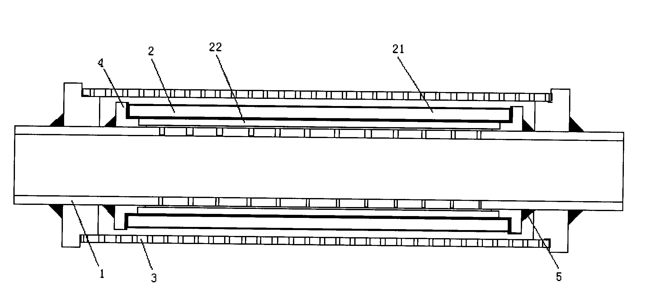
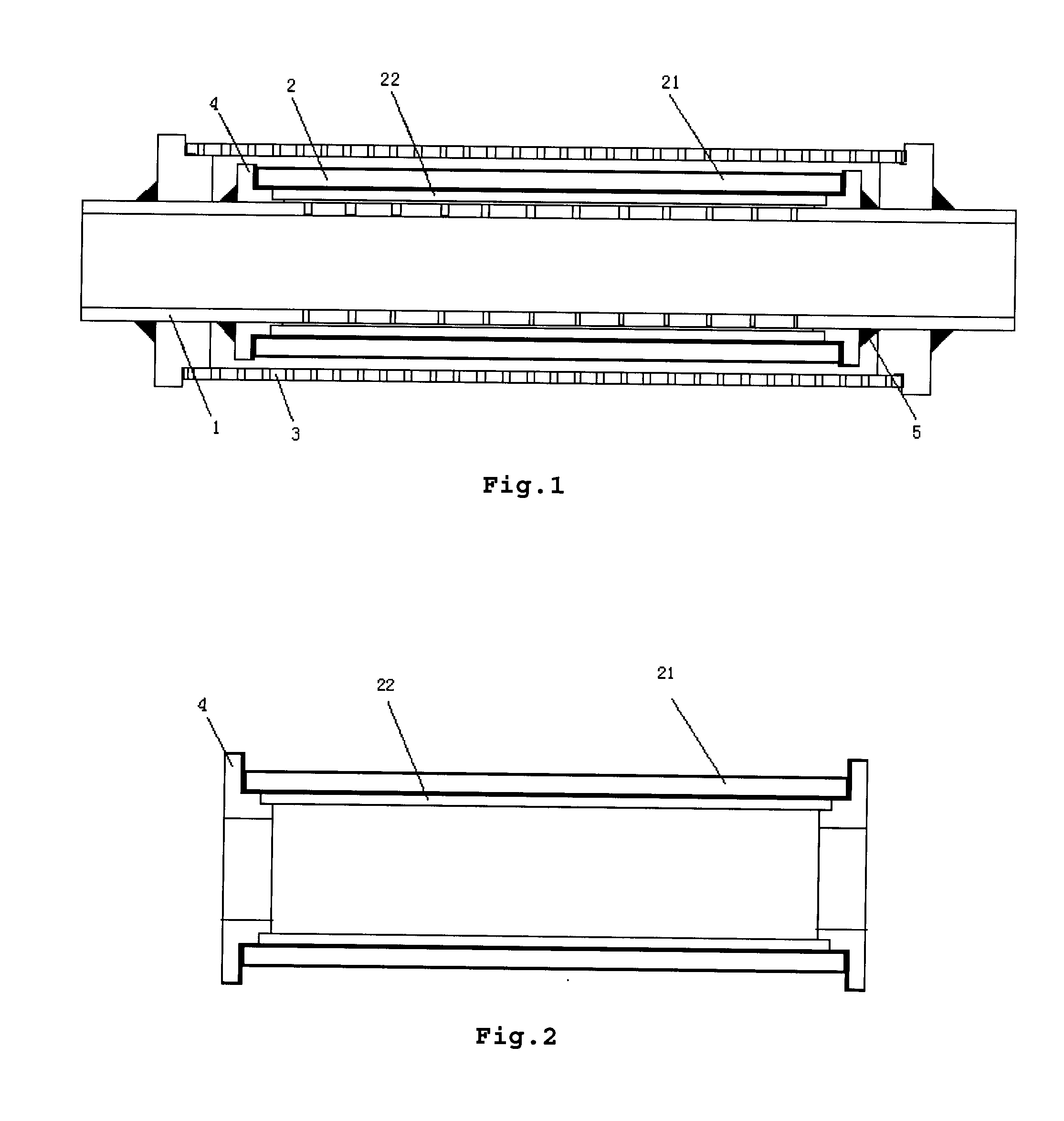
[0028]As shown in FIG. 1, it shows the screen manufactured by the present invention, which comprises a base pipe 1 with multiple penetrated holes in pipe wall, a filter sheath 2 and a protection jacket 3 with multiple leakage holes in pipe wall; wherein the filter sheath 2 covers the outside of the base pipe 2 and the jacket 3 covers the outside of filter sheath 2. And the detailed welding method is:

[0029]Step 1 wrapping the outside of a support sheath 22 with a metal filter net 21 and fixing the metal filter net 21 to the outside of the support sheath 22 by way of welding, so that the metal filter net 21 completely covers all filter holes of the support sheath 22 to form the filter sheath 2;

[0030]Step 2 fixing the filter sheath 2 to outside of the base pipe 1 such that the filter sheath 2 complete...


PUM

PropertyMeasurementUnit
pressureaaaaaaaaaa
pressureaaaaaaaaaa
sizeaaaaaaaaaa

Abstract

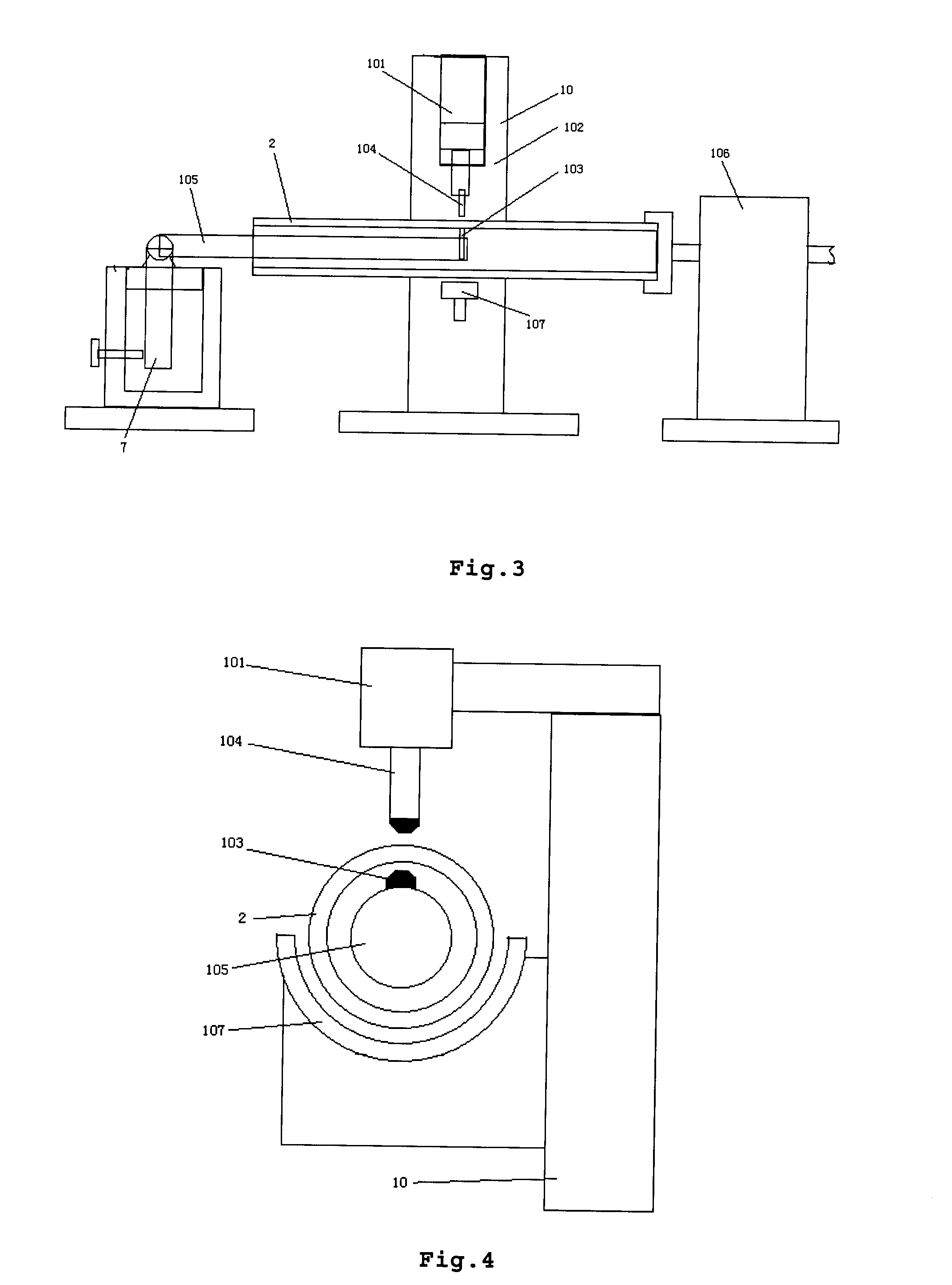
The present invention relates to a method for manufacturing a screen and welding apparatus thereof, putting a metal filter net around the outside of a support sheath and fixing the metal filter net to the outside of the support sheath by way of welding, such that the metal filter net completely covers all filter holes of the support sheath to form a filter sheath with; fixing the filter sheath to the outside of the base pipe and the filter sheath completely covering all penetrated holes on the base pipe; putting a jacket around the outside of the filter sheath and fixing it to the outside of the base pipe such that the jacket completely covers the outside surface of the filter area of the filter sheath. The present invention uses direct spot welding and seam welding technology to fix the metal net to the outside of the support sheath directly, eliminates leakage hole phenomena appearing on jointing parts of the metal net and forms the screen with multi-layer metal nets with improved sand control capability and life time. The present invention also discloses the apparatus for above-said screen to realize penetrated welding of the filter sheath so as to improve the welding quality of the metal net and lower the factory cost of the screen.

Description

CROSS-REFERENCE TO RELATED PATENT APPLICATIONS[0001]The present application is a divisional application of U.S. application Ser. No. 11 / 362,282, filed Feb. 27, 2006, the entire contents of which is incorporated herein by reference in its entirety.FIELD OF THE INVENTION[0002]The present invention relates to a method for manufacturing screen (or sieve tube) and welding apparatus thereof, particularly to a method for manufacturing screen made of filtering material including metal net by resistance spot welding or seam welding technology and welding apparatus thereof. It belongs to petroleum exploitation field.BACKGROUND OF THE INVENTION[0003]In petroleum and natural gas exploitation fields, in order to prevent sand in the oil-gas well from being brought to shaft or ground apparatuses together with oil-gas-water while sanding, in-well screen which could effectively filtrates oil-gas-water needed to be used. One hole in a segment of an in-well screen ranged from several decades to severa...

Claims


Application Information

Patent Timeline
Patent Type & Authority Applications(United States)
IPC IPC(8): B23K11/00
CPCB23K11/11B23K2201/06E21B43/084Y10T29/49602Y10T29/49604Y10T29/49968Y10T29/49929Y10T29/496B23K2101/06
Inventor HUANG, CHUNHONGCHEN, JICHU
Owner BEIJNG HINEN HITECH PETROLEUM TECH DEV
Learn More