Mapping a Client Signal into Transport Frames

a client signal and transport frame technology, applied in the field of optical communication network systems, can solve problems such as one or more channels being lost in the transport fram

Active Publication Date: 2009-10-01
INFINERA CORP
View PDF13 Cites 9 Cited by
  • Summary
  • Abstract
  • Description
  • Claims
  • Application Information

AI Technical Summary

Benefits of technology

[0014]Embodiments of the present invention provide a systems, devices, and methods in which a client signal is divided into a plurality of channels, mapped within transport frames, and combined into a WDM transport signal. These embodiments include intra-nodal redundancy that pr

Problems solved by technology

An intra-nodal failure may be a non-operational component within a node, such as the WDM t

Method used


Image

  • Mapping a Client Signal into Transport Frames
  • Mapping a Client Signal into Transport Frames
  • Mapping a Client Signal into Transport Frames

Examples


Embodiment Construction

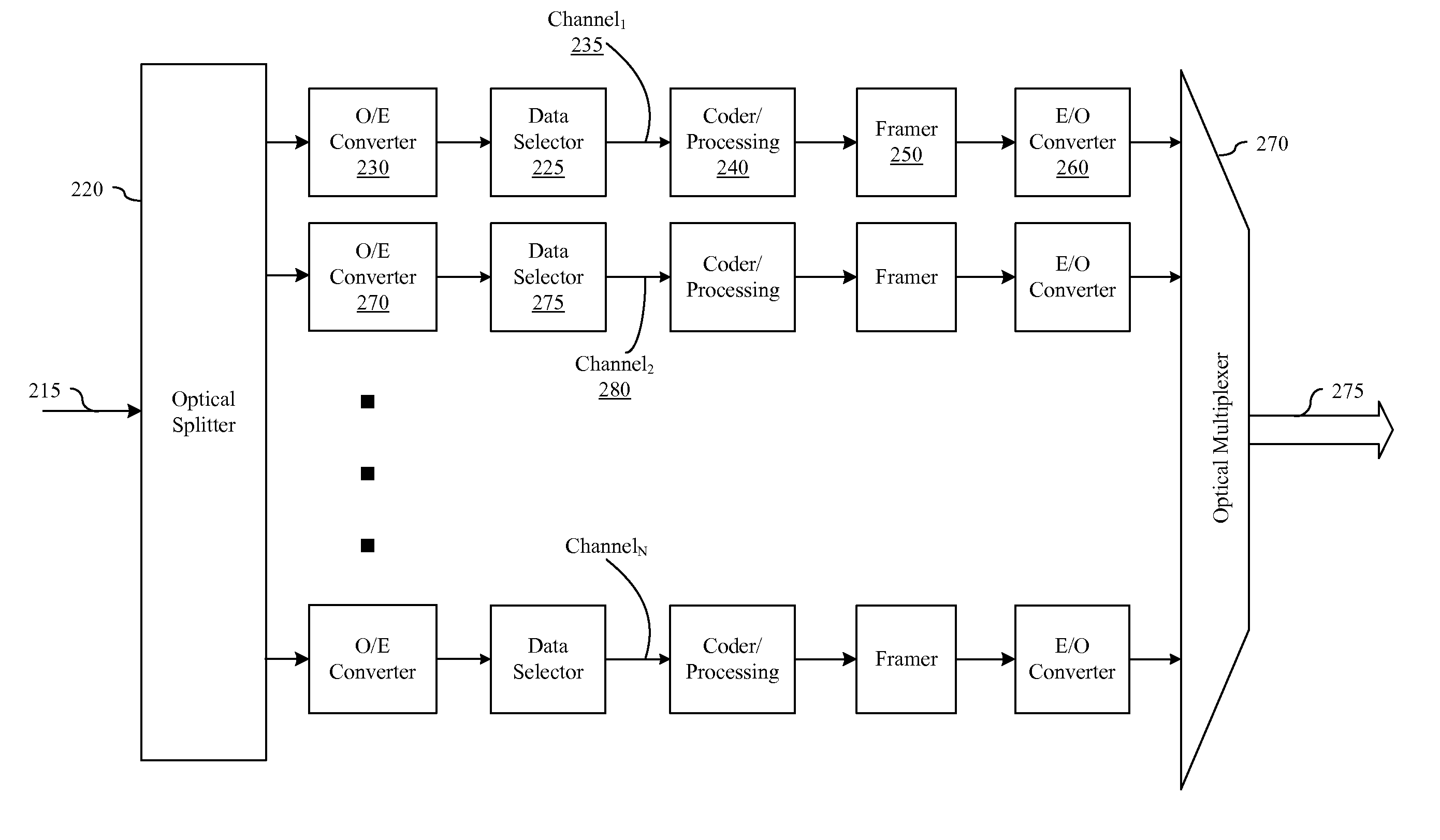
[0027]In the following description, for the purpose of explanation, specific details are set forth in order, by the use of concrete examples, to provide a sound understanding of the present invention. It will be apparent; however, that the present invention may be practiced without some or even all of those details, and it will be recognized that embodiments of the present invention, some of which are described below, may be incorporated into a number of different devices, systems, and methods. Structures, devices, and methods depicted in block diagram are merely illustrative of exemplary embodiments of the present invention and are included in that form in order to avoid obscuring essential teachings of the present invention.

[0028]Furthermore, connections between components in the figures are not restricted to connections that are effected directly. Instead, connections illustrated in the figures between components may be modified or otherwise changed through the addition thereto o...


PUM


Abstract

Embodiments of the present invention provide a systems, devices, and methods in which a client signal is divided into a plurality of channels, mapped within transport frames, and combined into a WDM transport signal. These embodiments include intra-nodal redundancy that protects against failure events within the transport transmitter. In particular, redundancy is provided within a network transport transmitter such that redundant paths are available so that electrical channels may be routed around a malfunctioning component within the transmitter.

Description

BACKGROUND[0001]A. Technical Field[0002]This invention relates generally to optical communication networking systems, and more particularly, to the transmission of high speed client signals across a transport network.[0003]B. Background of the Invention[0004]The capacity of transport systems is continually increasing to provide larger amounts of available bandwidth to clients. These transport systems are able to communicate large amounts of data using optical networking technologies. In certain systems, wavelength division multiplexed (hereinafter, “WDM”) transport systems communicate this data on multiple wavelengths between terminal nodes. These WDM systems offer a network provider scalable bandwidth without having to significantly expand the physical infrastructure of a network to realize this additional bandwidth.[0005]Certain transport systems are designed to receive a client signal, re-format the client signal and transmit this reformatted client signal over a long-haul connec...

Claims


Application Information

Patent Timeline
IPC IPC(8): H04J14/02
CPCH04J14/0227H04J14/0246H04J14/0297H04J14/0279
Inventor CHIANG, TING-KUANG
Owner INFINERA CORP
Why Eureka
Try Eureka