
Interspinous implant, tools and methods of implanting

a technology of interspinous implants and tools, applied in the field of interspinous implants, tools and methods of implanting, can solve the problems of inability to achieve the effects of reducing the risk of infection, profuse bleeding, and inherent negative side effects, and achieves the effects of reducing cost and operative time, reducing neural compression, and increasing the foraminal and thecal sac spa

Inactive Publication Date: 2009-09-24
COLLABCOM11
View PDF101 Cites 31 Cited by
  • Summary
  • Abstract
  • Description
  • Claims
  • Application Information

AI Technical Summary

Benefits of technology

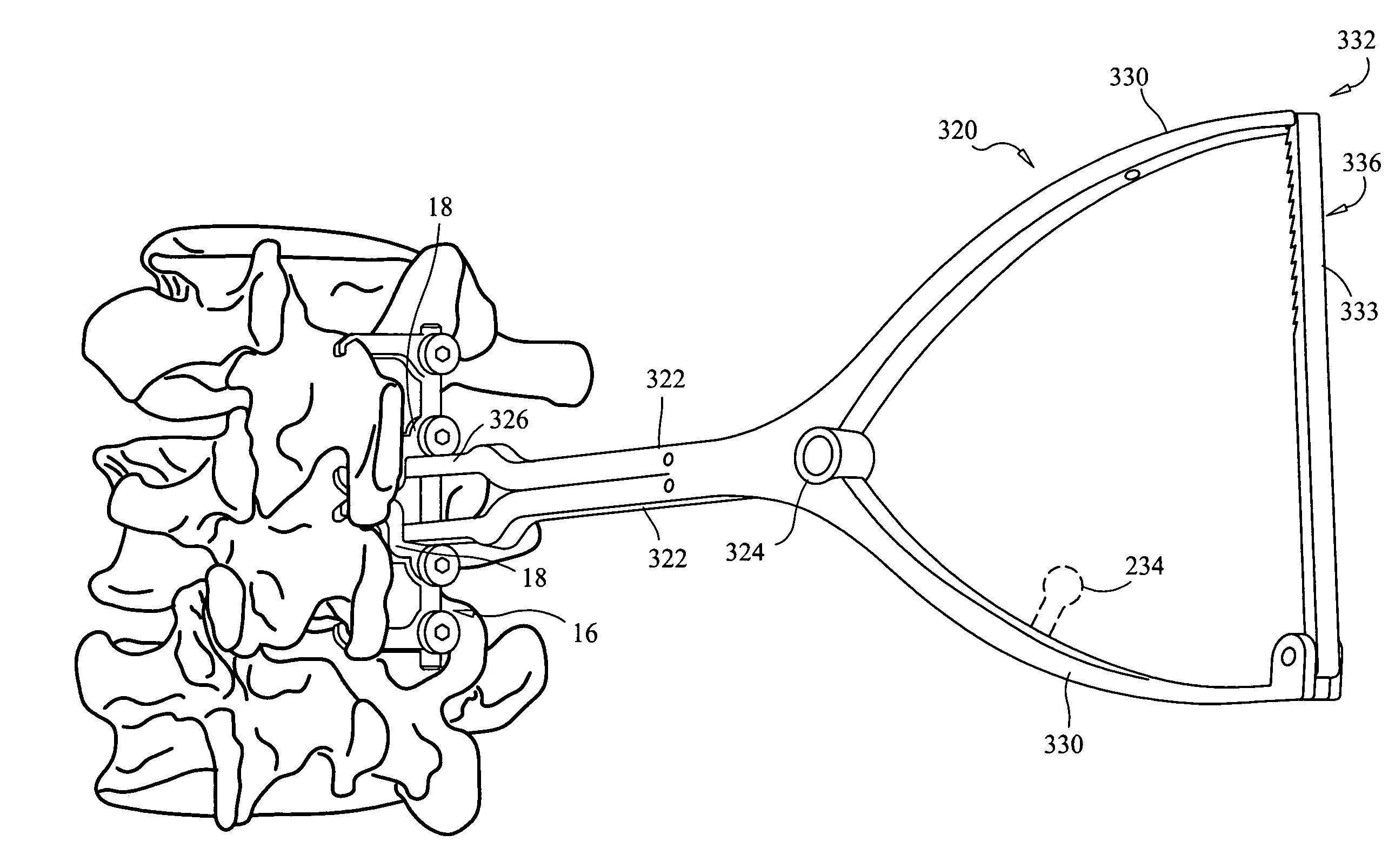
[0006]The present invention provides devices, tools and methods for minimal implantation of a dynamic interspinous implant device to placed controlled distraction between the spinous processes to increase the foraminal and thecal sac space. Devices according to the present invention can be placed with a small incision. Additionally, multi-level implants (i.e., spanning more than one disc space) can be placed, thereby greatly reducing cost and operative time when treating multiple degenerative or stenotic levels. The device can be used to apply micro-compression. This can stabilize the segment so that open micro-decompressions to alleviate the neural compression and result in stabilization of the segment with or without formal spinal fusion. Additionally or alternatively, devices described herein may be combined with fusion or can be used for degenerative disk disease treatment for stabilization of a segment alone, thereby providing dynamic stabilization. A device as described herein can stabilize a segment for fusion. Bone grafting fusions can be implanted along with the device, wherein pedicle screw fixation is not required, and the device according to the present invention maintains the stability of the segment so that bone grafting materials can fuse with the vertebral bones, thereby providing rigid stabilization. The use of flexible rods or connectors with a device of the present invention can be used for motion preservation and for fusion.
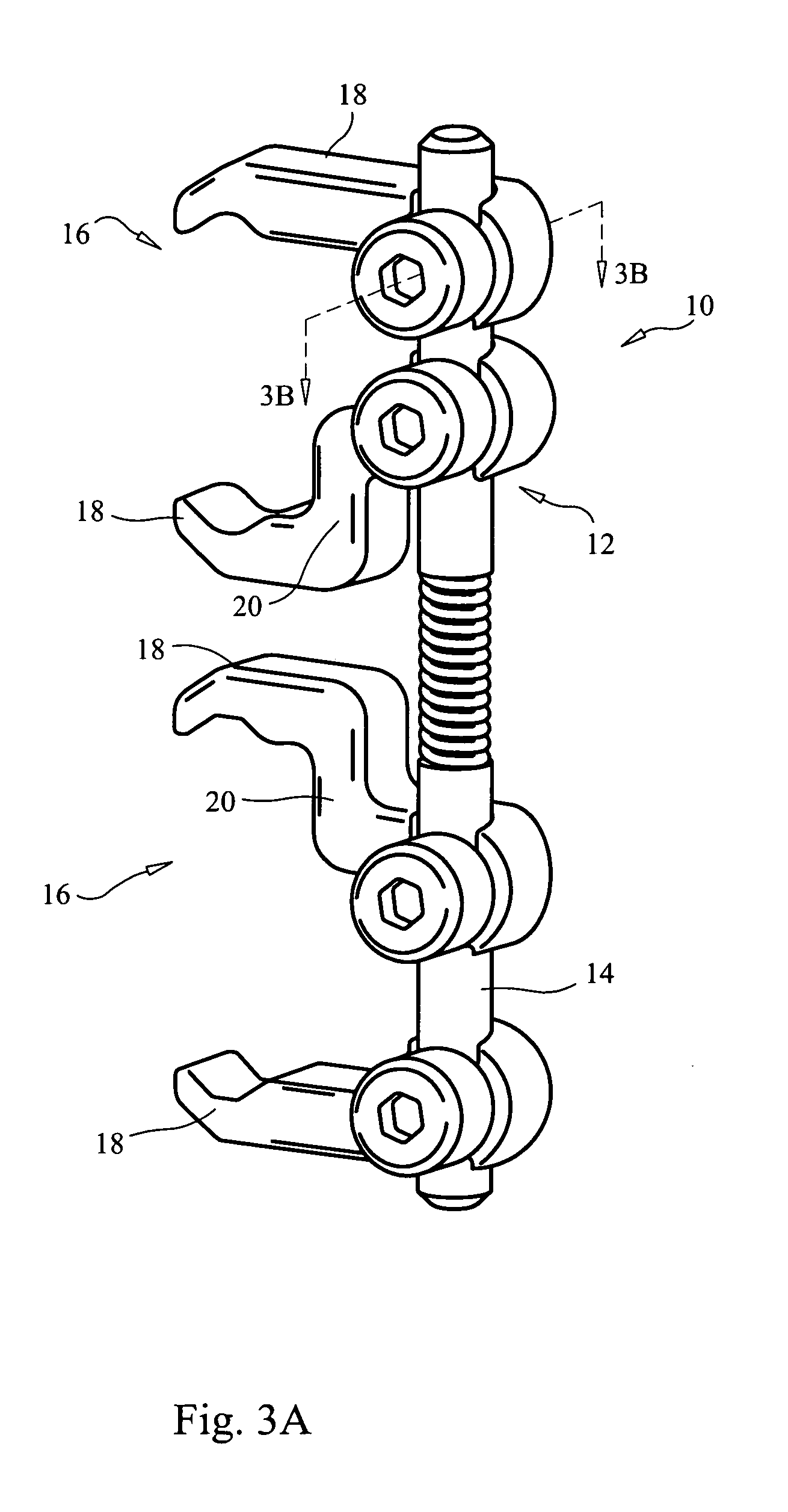
[0046]A kit for treatment of spinal disorders is provided, including: a device having: a main body including a shaft having a longitudinal axis; a first clamping mechanism having first and second jaws configured to clamp a spinous process of a first vertebra; a second clamping mechanism having third and fourth jaws configured to clamp a spinous process of a second vertebra; the first, second, third and fourth jaws extending transversely from the main body, wherein at least two of the jaws are releasably mounted to the shaft and are mountable to and removable from the shaft by relative movement between the respective jaw and the shaft in a direction normal to a longitudinal axis of the shaft; and a component for facilitating fusion of the adjacent vertebrae while the device is implanted between the spinous processes.

Problems solved by technology

Many potentially negative side effects are inherent in this form of treatment, including profuse bleeding, substantial risk of infection, potential nerve damage sometimes leading to paralysis and / or bladder / bowel dysfunction, dural tears, persistent fluid leakage, arachnoiditis, continuing chronic pain, non-union (if fusion is performed), fusion hardware failure, donor site pain, adjacent segment disease, long operation times, and substantial operation costs.
Additionally, there are the inherent general risks of the surgical procedure and the medical risks including, but not limited to: bleeding, infection, nerve or vessel damage, risks of anesthesia, death, need for further surgery, iatrogenic instability, epidural hematoma, failure of implants and / or associated hardware, misplacement of implants and hardware, migration of implants and hardware, heart attack, stroke, deep venous thrombosis, pulmonary embolism, spinal cord and nerve damage, reflex sympathetic dystrophy, sexual dysfunction, positioning problems, brachial plexus injuries, traction injuries, swallowing difficulties, problems with vocal cords, airway obstruction, postoperative swelling, need for prolonged intubation, persistent dural fistula, paralysis, blindness, no relief of current symptoms, possible development of new symptoms, possible worsening of current symptoms, possible need for intraoperative change of procedure, possible need for fusion of the spine as determined intraoperatively, and other rare risks not named above.
Further, many of these devices are rigid, inflexible and / or non-adjustable wedge-like implants that require dissection of muscle tissue and / or ligaments such as the supraspinous ligament and interspinous ligament.
Other attempts have been made at providing a dynamic stabilization device, but these attempts have generally required attachment to the pedicles, which typically not only have the drawbacks associated therewith as noted above (large, bilateral incisions, etc.), but also, these types of implants compromise revision strategies when they fail.
The attachment of pedicle-based dynamic stabilization can result in loosening of one or more of the pedicle screws used to attach the stabilizer to the pedicles, which can result in failure of fixation.
This can preclude the salvage of pedicle screws for revision surgery and thus require more aggressive surgery.
Other complications that can result from pedicle-based dynamic stabilizer arrangements include, but are not limited to: debris resulting from wear, and / or cut-out of pedicle screws into the spinal canal, which can result in neurological deterioration.

Method used


Image

  • Interspinous implant, tools and methods of implanting
  • Interspinous implant, tools and methods of implanting
  • Interspinous implant, tools and methods of implanting

Examples


Embodiment Construction

[0068]Before the present devices, tools, systems and procedures are described, it is to be understood that this invention is not limited to particular embodiments described, as such may, of course, vary. It is also to be understood that the terminology used herein is for the purpose of describing particular embodiments only, and is not intended to be limiting, since the scope of the present invention will be limited only by the appended claims.

[0069]Where a range of values is provided, it is understood that each intervening value, to the tenth of the unit of the lower limit unless the context clearly dictates otherwise, between the upper and lower limits of that range is also specifically disclosed. Each smaller range between any stated value or intervening value in a stated range and any other stated or intervening value in that stated range is encompassed within the invention. The upper and lower limits of these smaller ranges may independently be included or excluded in the range...


PUM


Abstract

Devices, tools and methods for minimally invasive implantation of a dynamic interspinous implant device for distracting between spinous processes and providing dynamic stabilization. One exemplary device includes a main body including a shaft having a longitudinal axis; a first clamping mechanism having first and second jaws configured to clamp a spinous process of a first vertebra, and a second clamping mechanism having third and fourth jaws configured to clamp a spinous process of a second vertebra. The first, second, third and fourth jaws extend transversely from the shaft and at least two of two of the jaws are releasably mounted to the shaft and are mountable to and removable from the shaft by relative movement between the respective jaw and the shaft in a direction normal to a longitudinal axis of the shaft. The shaft has sufficient columnar strength to maintain distraction between the first and second vertebrae via the clamps, while also allowing at least one of the relative movements between the first and second vertebrae selected from the movements including lateral bending, flexion, extension and axial rotation.

Description

BACKGROUND OF THE INVENTION[0001]With the aging of the population there has occurred an increase in the incidences of degenerative diseases of the spine and this trend is expected to continue with the continuing increase in the percentage of elderly people in the population. Spinal stenosis is one of the most frequent forms of spinal degenerative disease observed. One conventional treatment of spinal stenosis has been laminectomy and decompression of compressed vertebrae and additionally fusing the treated vertebrae if instability exists. Many potentially negative side effects are inherent in this form of treatment, including profuse bleeding, substantial risk of infection, potential nerve damage sometimes leading to paralysis and / or bladder / bowel dysfunction, dural tears, persistent fluid leakage, arachnoiditis, continuing chronic pain, non-union (if fusion is performed), fusion hardware failure, donor site pain, adjacent segment disease, long operation times, and substantial opera...

Claims


Application Information

Patent Timeline
Patent Type & Authority Applications(United States)
IPC IPC(8): A61B17/00A61B17/58A61F2/44
CPCA61B17/7047A61B2017/0256A61B17/7062A61B17/7056
Inventor WANG, JEFFREY CHUNSCIOSCIA, THOMAS NEILSLATTERY, ADRIANCANNON, ALAN W.
Owner COLLABCOM11
Learn More