
Image capturing apparatus and method for controlling image capturing

Active Publication Date: 2009-09-24
FUJIFILM CORP
View PDF15 Cites 34 Cited by
  • Summary
  • Abstract
  • Description
  • Claims
  • Application Information

AI Technical Summary

Benefits of technology

[0006]The present invention has been made in view of the above circumstances and has an object to provide an image capturing apparatus and a method for controlling image capturing which improve usability at shots by oneself, a third party and a self-timer by assisting the photographing to make a good composition even when the object is more than one person.
[0045]According to any aspects of the present invention, it possible to provide an image capturing apparatus and a method for controlling image capturing which improve usability at shoots by oneself, a third party and a self-timer by assisting image capturing in order to make a good composition even when the object includes more than one person.

Problems solved by technology

However, the apparatus of Japanese Patent Application Laid-Open No. 2007-142866 has a problem that it is not possible to assist photographing so as to make a good composition when the object is more than one person.

Method used


Image

  • Image capturing apparatus and method for controlling image capturing
  • Image capturing apparatus and method for controlling image capturing
  • Image capturing apparatus and method for controlling image capturing

Examples


first embodiment

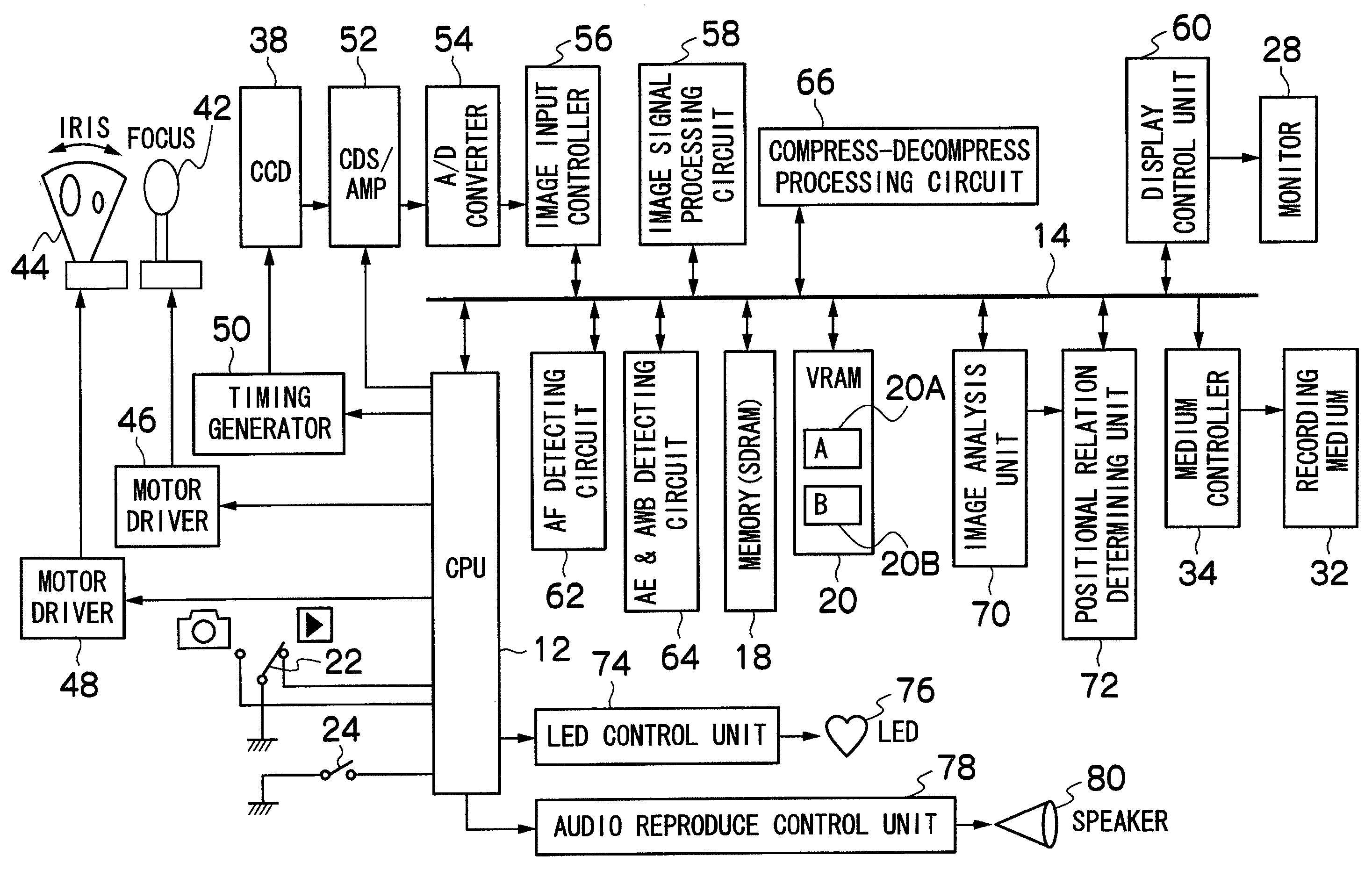
[0059]FIG. 1 is the block diagram of the first embodiment of the digital camera 1 according to the present invention.

[0060]An entire action of the digital camera 1 is integrally controlled by a central processing unit (CPU) 12.

[0061]The CPU 12 works as a control device to control the digital camera 1 according to a predetermined program and as an arithmetic processing device to carry out various arithmetic operations such as an automatic exposure (AE) operation, an autofocus (AF) operation, and a white balance (WB) adjusting operation.

[0062]A CCD pixel defect information, various constants, information and the like related to the camera action are stored in a ROM (not shown) which is connected to CPU 12 via a bus 14, as well as various data needed for CPU 12 to execute a program and control.

[0063]Also, a memory (SDRAM) 18 is used as a temporary storage area of an image data and audio data as well, in addition to as a developing area of the program and an arithmetic processing area o...

second embodiment

[0107]Referring to FIG. 7 to FIG. 8C, the couple shot timer mode of a second embodiment is explained. With the couple shot timer mode of the second embodiment, the positional relation determining unit 72 calculates the distance between the human faces and the degree of overlapping of the detected human faces. Then, starting the notice process and the timer shooting is controlled based on the degree of overlapping of the detected human faces.

[0108]First, the degree of overlapping of the detected human faces is explained. As shown in FIG. 7, the face boxes of the two chosen representative faces are 120 and 121. When the area of the face box 120 is signified as S1, the area of the face box 121 is signified as S2, and the area of overlapping of the face boxes 120 and 121 is signified as S3 here, the degree of overlapping can be shown below.

The degree of overlapping=S3÷(S1+S2)×100 [%]  [Formula 3]

[0109]The degree of overlapping which is calculated in this way and the predetermined thresh...

third embodiment

[0114]Referring to FIGS. 9A to 10C, the couple shot timer mode of a third embodiment is explained. The positional relation determining unit 72 calculates the distance between the human faces and also the difference of inclination of the detected human faces at the couple shot timer mode of the third embodiment. The notice process and starting of the timer shooting are controlled based on the distance between the human faces and the difference of inclination of the faces.

[0115]First, the difference of inclination of the faces is described. As shown in FIGS. 9A and 9B, the inclinations of the two chosen representative faces are calculated. The inclination of the face is defined by the angle formed with a line connecting a right and a left eyes and the horizontal line. Also, the angle inclined in a clockwise direction is signed as plus and the angle inclined in a counter-clockwise direction is signed as minus. When the inclination of the face on the right as facing the drawing is signi...


PUM


Abstract

An image capturing apparatus includes: an image capturing device which receives an optical image of an object subjected to light via an image capturing lens and converts the optical image into an image signal; a face detecting device which detects a plurality of human faces from the image signal; a face distance calculating device which calculates a distance between the detected human faces; a notice device which gives a notice corresponding to the calculated distance between the human faces; a timer shot device which performs a real shooting after an elapse of a first predetermined time since a shooting instruction; and a control device which gives the shooting instruction to the timer shot device when the calculated distance between the human faces is less than a predetermined value. Accordingly, even when the shooting object includes persons, a well composed shooting can be easily realized.

Description

BACKGROUND OF THE INVENTION[0001]1. Field of the Invention[0002]The present invention relates to an image capturing apparatus and a method for controlling image capturing. More specifically, the invention relates to an image capturing apparatus and a method for controlling image capturing which display an object and output an audio in accordance with a positional relation of the object.[0003]2. Description of the Related Art[0004]An apparatus which does a composition assist by detecting a person from an image captured with an image capturing apparatus is known. For example, Japanese Patent Application Laid-Open No. 2007-142866 discloses an image capturing apparatus which displays a mark showing a direction in which the image capturing apparatus should be moved in order to obtain a human face within an image capturing range, when the human face is out of the image capturing range. According to the apparatus of Japanese Patent Application Laid-Open No. 2007-142866, it is possible to o...

Claims


Application Information

Patent Timeline
IPC IPC(8): H04N5/228G06K9/00
CPCG06K9/00255G06K9/00912H04N5/232H04N2101/00H04N5/23222H04N5/23293H04N5/23219G06V40/166G06V40/67H04N23/64H04N23/611
Inventor NISHIJIMA, MASAKAZU
Owner FUJIFILM CORP
Learn More