Timing Control Apparatus
- Summary
- Abstract
- Description
- Claims
- Application Information
AI Technical Summary
Benefits of technology
Problems solved by technology
Method used
Image

Examples
first embodiment
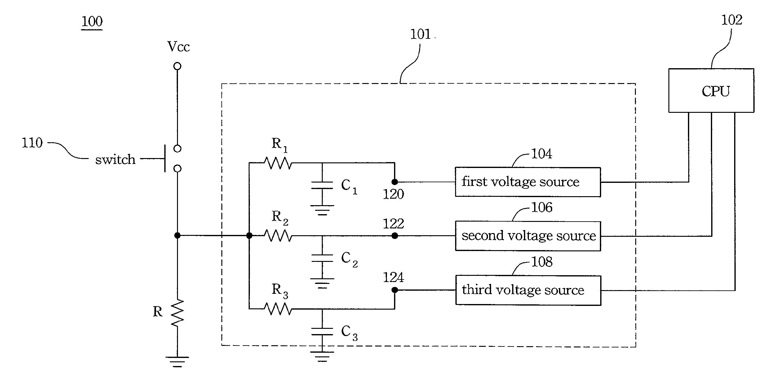
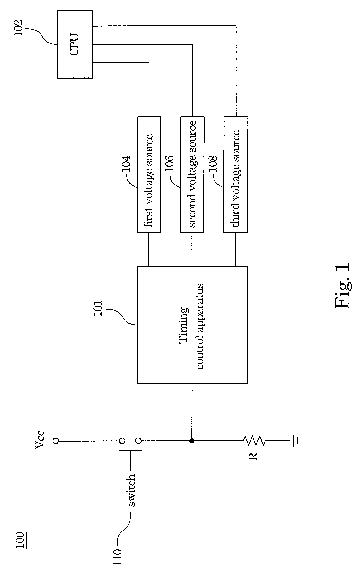
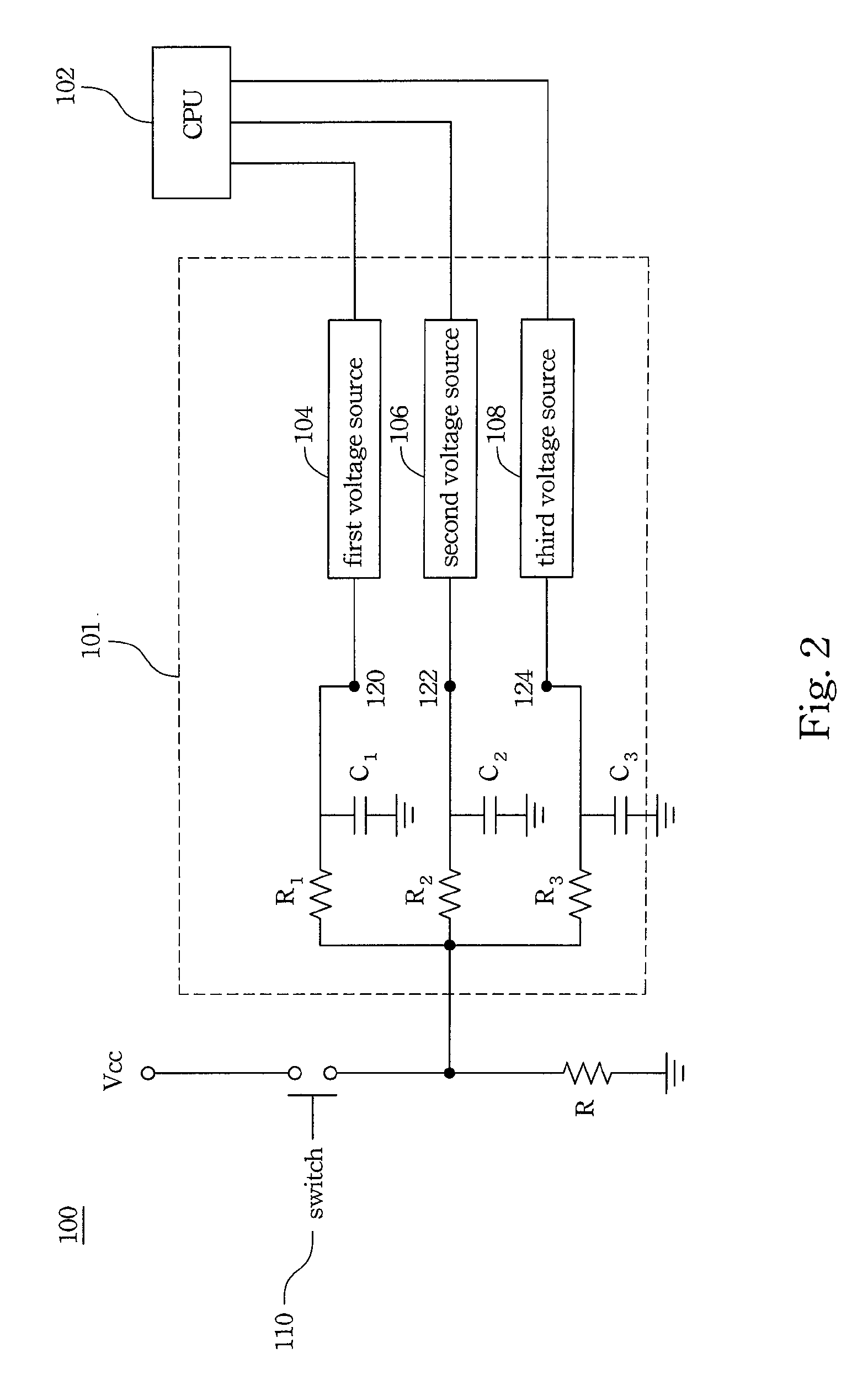
[0012]FIG. 1 is a schematic diagram of an electronic system with a timing control apparatus according to the present invention. The timing control apparatus 101 sequentially turns on or turns off the voltage sources of a central processing unit (CPU) 102. However, in other embodiments, the timing control apparatus 101 sequentially turns on or turns off the voltage sources of other electronic devices. Moreover, the voltage sources can supply the same voltage level or different voltage levels respectively.
[0013]According to an embodiment, the electronic system 100 includes a timing control apparatus 101, a central processing unit 102, a first voltage source 104, a second voltage source 106, a third voltage source 108 and a switch 110. The switch 110 switches the power Vcc. The timing control apparatus 101 controls the on / off timing of the first voltage source 104, the second voltage source 106 and the third voltage source 108 to provide voltage to the central processing unit 102 based...
second embodiment
[0018] after the power Vcc is connected to the system 200 by the switch 110, the switch S4 is turned on to ground the gate electrodes of the switches S1, S2 and S3. Therefore, the switches S1, S2 and S3 are turned off. These discharging routes controlled by the switches S1, S2 and S3 do not work. In this case, the power Vcc charges the capacitors C1, C2 and C3 through the resistor R1, R2 and R3. The time for charging the capacitors C1, C2 and C3 can be adjusted by varying the resistance of the resistor R1, R2 and R3 and the capacitance of the capacitors C1, C2 and C3. Therefore, the first voltage source 104, the second voltage source 106 and the third voltage source 108 can provide voltages to the central processing unit 102 based on a specific timing.
[0019]On the other hand, after the switch 110 cuts off the connection between the power Vcc and the system 200, the gate electrode of the switch S4 is grounded to cause the gate electrodes of the switches S1, S2 and S3 are connected to...
third embodiment
[0025]FIG. 4 is a schematic diagram of an electronic system with a timing control apparatus according to the present invention. The switch 410 of the system 400 is a pulse switch that outputs a pulse signal. In this embodiment, a Flip-Flop connects with the switch 410 to transform the pulse signal to a signal with fixed high level or low level. This signal is sent to the timing control apparatus 101.
PUM
 Abstract
Description
Claims
Application Information
 - R&D
- Intellectual Property
- Life Sciences
- Materials
- Tech Scout
- Unparalleled Data Quality
- Higher Quality Content
- 60% Fewer Hallucinations
Browse by: Latest US Patents, China's latest patents, Technical Efficacy Thesaurus, Application Domain, Technology Topic, Popular Technical Reports.
© 2025 PatSnap. All rights reserved.Legal|Privacy policy|Modern Slavery Act Transparency Statement|Sitemap|About US| Contact US: help@patsnap.com