
Schmitt trigger having variable hysteresis and method therefor

a trigger and variable technology, applied in the field of schmitt triggers, can solve the problems of low and high threshold voltage, adversely changing the hysteresis window,

Inactive Publication Date: 2009-09-24
FREESCALE SEMICON INC
View PDF3 Cites 73 Cited by
  • Summary
  • Abstract
  • Description
  • Claims
  • Application Information

AI Technical Summary

Problems solved by technology

However, various factors such as manufacturing process variations and temperature changes may affect the low and high threshold voltages and adversely change the hysteresis window.

Method used


Image

  • Schmitt trigger having variable hysteresis and method therefor
  • Schmitt trigger having variable hysteresis and method therefor
  • Schmitt trigger having variable hysteresis and method therefor

Examples


Embodiment Construction

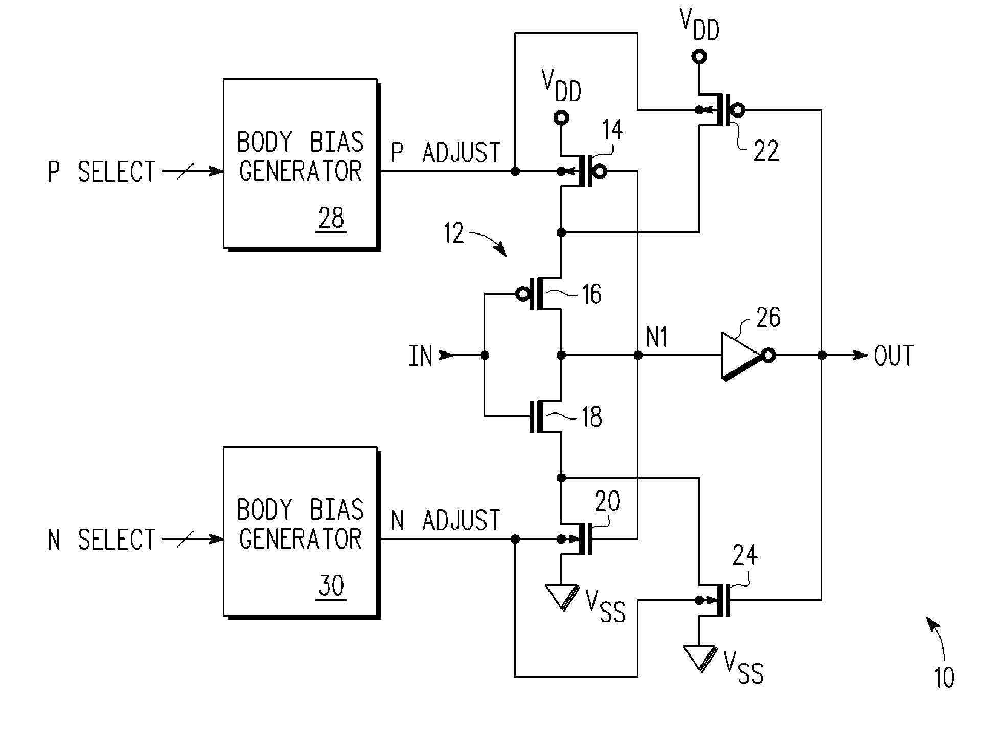
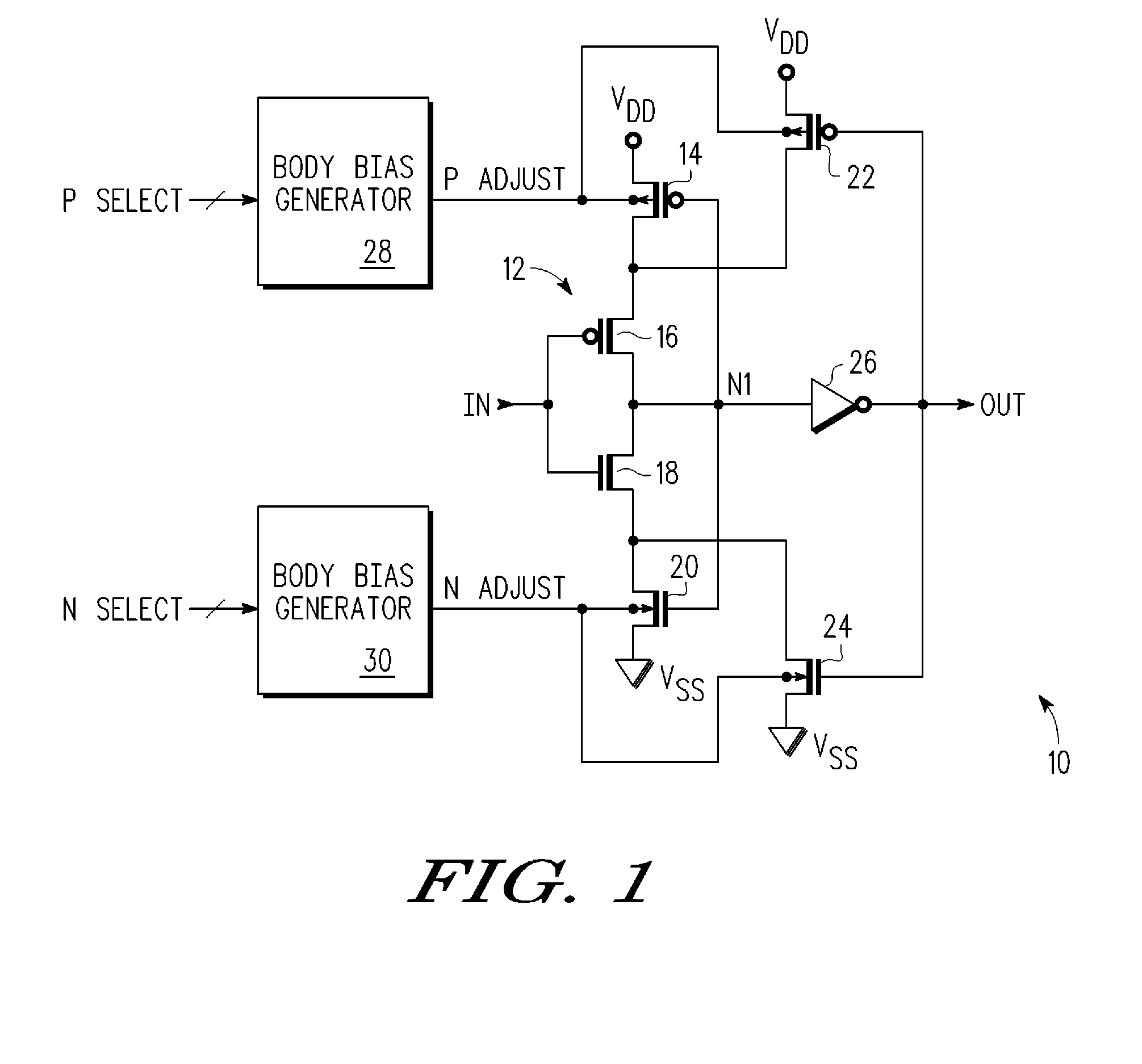
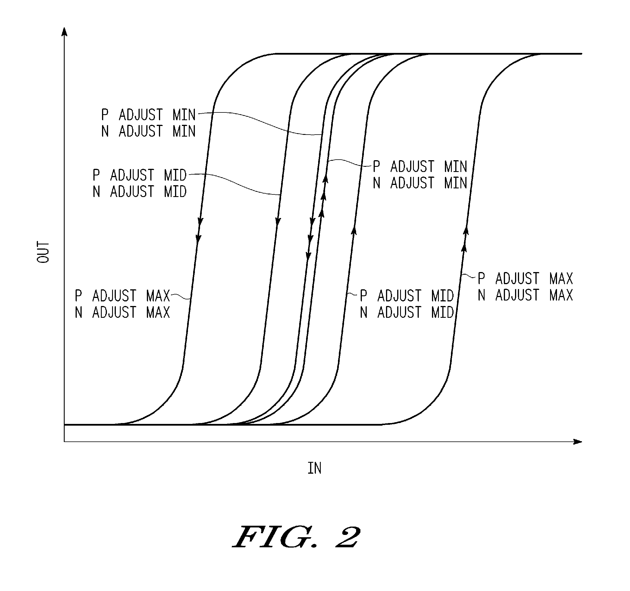
[0009]Generally, there is provided, a Schmitt trigger having a variable hysteresis window. The hysteresis window is adjusted by changing a threshold voltage of the hysteresis producing transistors of the Schmitt trigger. The threshold voltage is changed by selectively adjusting a body bias voltage of the hysteresis producing transistors. Adjusting the hysteresis window allows the hysteresis window to be controlled in response to factors such as manufacturing processing variations and temperature changes.

[0010]In one aspect, there is provided, a Schmitt trigger comprising: a first inverter having an input and an output; a second inverter having an input coupled to the output of the first inverter and an output; bias means for providing a first bias voltage on a first output terminal, wherein a magnitude of the bias voltage is selectable by a first input signal; and a first transistor having a first current electrode coupled to a first power supply terminal, a control electrode couple...


PUM


Abstract

A Schmitt trigger has a first inverter, a second inverter, a bias means, and a transistor. The inverter has an input and an output. The second inverter has an input coupled to the output of the first inverter and has an output. The bias means provides a first bias voltage on a first output terminal. A magnitude of the bias voltage is selectable by a first input signal. The transistor has a first current electrode coupled to a first power supply terminal, a control electrode coupled to the output of the second inverter, a second current electrode coupled to the output of the first inverter, and a body coupled to the first output terminal. Selectability of the magnitude of the bias voltage provides selectability of the hysteresis of the Schmitt trigger.

Description

BACKGROUND[0001]1. Field[0002]This disclosure relates generally to Schmitt triggers, and more specifically, to a Schmitt trigger having variable hysteresis and method therefor.[0003]2. Related Art[0004]Schmitt triggers are used in a variety of integrated circuit applications requiring hysteresis. For example, in one application, a Schmitt trigger is used to convert a sinusoidal input signal, such as a clock, to a pulse train. A Schmitt trigger has a hysteresis window comprising a low threshold voltage and a high threshold voltage. The high threshold voltage determines a transition point for a low-to-high signal transition, and the low threshold voltage determines a transition point for a high-to-low signal transition. In some applications, it is important that the low and high threshold voltages be precisely controlled. However, various factors such as manufacturing process variations and temperature changes may affect the low and high threshold voltages and adversely change the hys...

Claims


Application Information

Patent Timeline
Patent Type & Authority Applications(United States)
IPC IPC(8): H03K3/00
CPCH03K2217/0018H03K3/3565
Inventor RAMARAJU, RAVINDRARAJBURCH, KENNETH R.
Owner FREESCALE SEMICON INC
Learn More