
Feedback controlled illumination system having an array of leds, and a detector among the leds

Inactive Publication Date: 2009-09-24
KONINKLIJKE PHILIPS ELECTRONICS NV
View PDF4 Cites 8 Cited by
  • Summary
  • Abstract
  • Description
  • Claims
  • Application Information

AI Technical Summary

Benefits of technology

[0005]It is an object of the present invention to provide an illumination system that eliminates the above-mentioned drawbacks of the prior art illumination system.
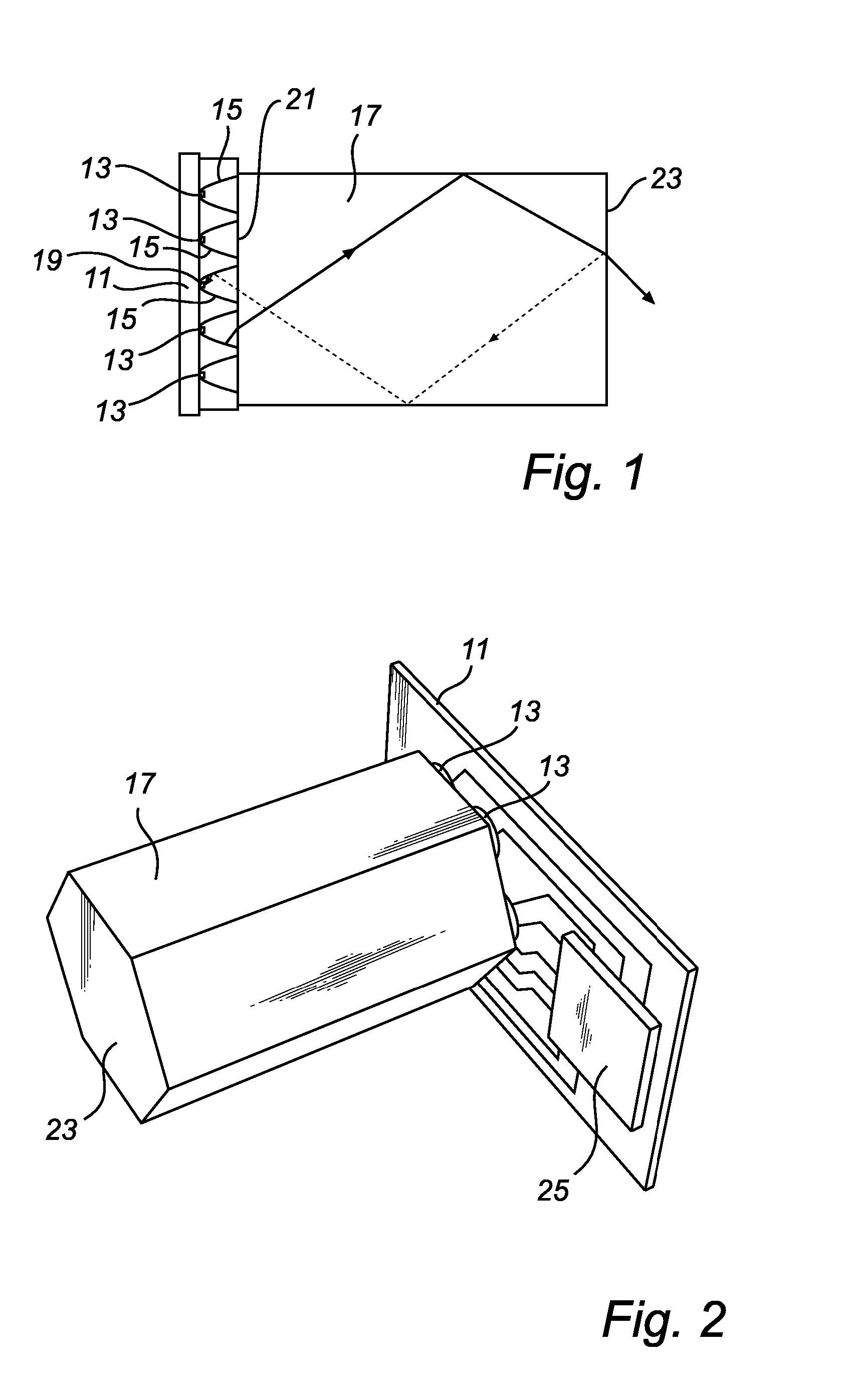
[0009]Thus, the reflected light rays are detected by the detector. Since this reflection occurs in any case, and since there is no additional reflective element the losses are minimised.
[0010]Additionally, the use of a light mixing element in combination with the collimators where the light emitted by the LEDs that reaches the detector has travelled at least twice through the total length thereof, is advantageous. Thereby there is provided optimal conditions for sensing the light from the various LEDs with equal weight factors, while at the same time minimizing the overall dimensions of the system. Thus, the detected light is a best possible sample of the light actually emitted by the LEDs.
[0011]As an additional advantage, since the detector is arranged within a light shield, it is shielded from any stray light that originates directly from neighbouring LEDs.
[0012]In accordance with an embodiment of the illumination system of this invention, as defined in claim 2, several detectors are arranged each within a respective light shield. Ideally the reflected light that reaches the LED / detector area is absolutely homogeneous, while in practise there might be minor variations. This embodiment has the advantage of collecting a larger part of the reflected fraction, which increases the precision of the control even more.
[0016]In an embodiment of the illumination system according to the invention, as defined in claim 6, the round cross sectional shape provides for an optimal collimation of the light emitted by the LED.

Problems solved by technology

However, it still is likely that the detected light is not optimally homogenised.
Further, it is undesirable to position a partially reflecting element in the path of the light output both as regards the complexity of the illumination system structure and as regards the additional loss, in the intensity of the light emitted from the illumination system, that is introduced by the reflective element.

Method used


Image

  • Feedback controlled illumination system having an array of leds, and a detector among the leds
  • Feedback controlled illumination system having an array of leds, and a detector among the leds
  • Feedback controlled illumination system having an array of leds, and a detector among the leds

Examples


Embodiment Construction

[0025]As shown in FIG. 1, one embodiment of the illumination system comprises a PCB (Printed Circuit Board) 11, an array of LEDs 13, where the LEDs 13 are positioned symmetrically on the PCB 11, a plurality of collimators 15, a light mixing element 17, and a detector 19, which is arranged within a light shield 15. The light shield shields the detector 19 from direct light from neighbouring LEDs 13 while admitting light that has been reflected internally of the mixing element 17 as will be further explained below. Each LED 13 is arranged in, and thus encircled by, a separate one of the collimators 15. Thus, one collimator 15 is provided for each LED 13. However, there is one more collimator 15, which is used as the light shield for the detector 19. In principle, the detector can be placed in any one of the collimators 15 without consequences for the correct functioning. However, to obtain the shortest possible light mixing element 17 it is advantageous to distribute the various LEDs ...


PUM


Abstract

The present invention relates to an illumination system having an array of differently coloured LEDs, a plurality of collimators, wherein each collimator holds at least one LED, a light mixing element, arranged to mix light generated by the LEDs into a mixed light that is emitted from the illumination system, and a control system for controlling the colour balance of the mixed light. The control system comprises a detector, which is placed among said collimators and encircled by a light shield. The detector detects a fraction of the mixed light that is reflected at an exit window of the mixing element. In this structure the detected light twice passes the mixing element, which provides for a proper mixing of the different colours as well as a proper homogenisation of the light.

Description

FIELD OF THE INVENTION[0001]The present invention relates to an illumination system comprising an array of different coloured LEDs (Light Emitting Diodes) a plurality of collimators, collimating light from the LEDs, a detector detecting a fraction of the light output of the illumination system, and a control system for controlling the colour balance of the light output.BACKGROUND OF THE INVENTION[0002]When designing an illumination system with different coloured LEDs a central question is how to obtain a desired colour balance of light emitted from the illumination system. Due to variations in the output of the LEDs over time even under constant operating conditions, e.g. differential ageing for the different colours and even for LEDs emitting the same colour, variation in the output of the LEDs with variation in operating conditions like drive current and temperature, and variations in the sensitivity of individual LEDs for variation of the operating conditions, and a complex struc...

Claims


Application Information

Patent Timeline
IPC IPC(8): H05B37/02H01L33/00H01L33/48
CPCF21S10/02F21Y2101/02F21V23/0457G02B6/0031G02B6/0068G02B6/0028F21Y2115/10
Inventor SORMANI, JOSEPH LUDOVICUS ANTONIUS MARIAHOELEN, CHRISTOPH GERARD AUGUST
Owner KONINKLIJKE PHILIPS ELECTRONICS NV
Learn More