Cooling/lubricating device for machine tool feed shaft
- Summary
- Abstract
- Description
- Claims
- Application Information
AI Technical Summary
Benefits of technology
Problems solved by technology
Method used
Image
Examples
Embodiment Construction
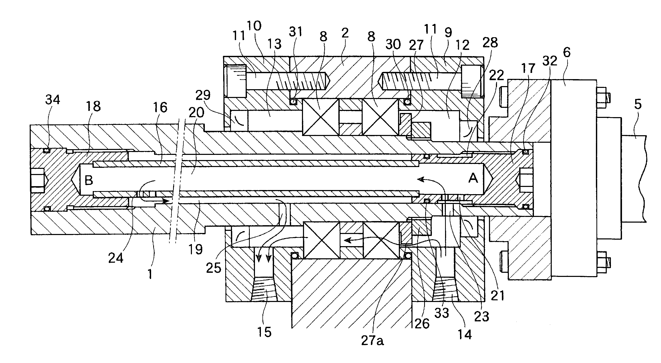
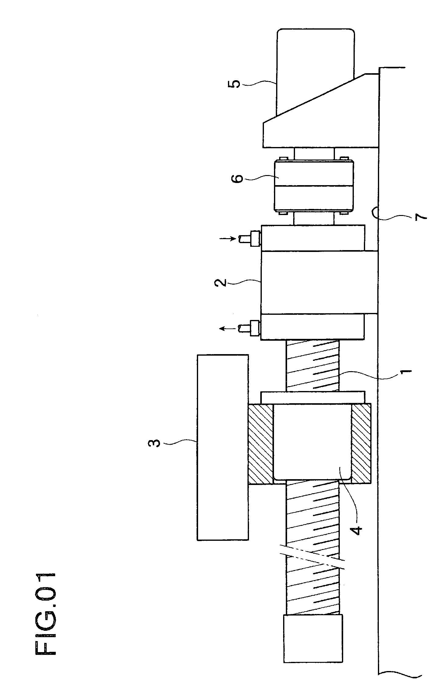
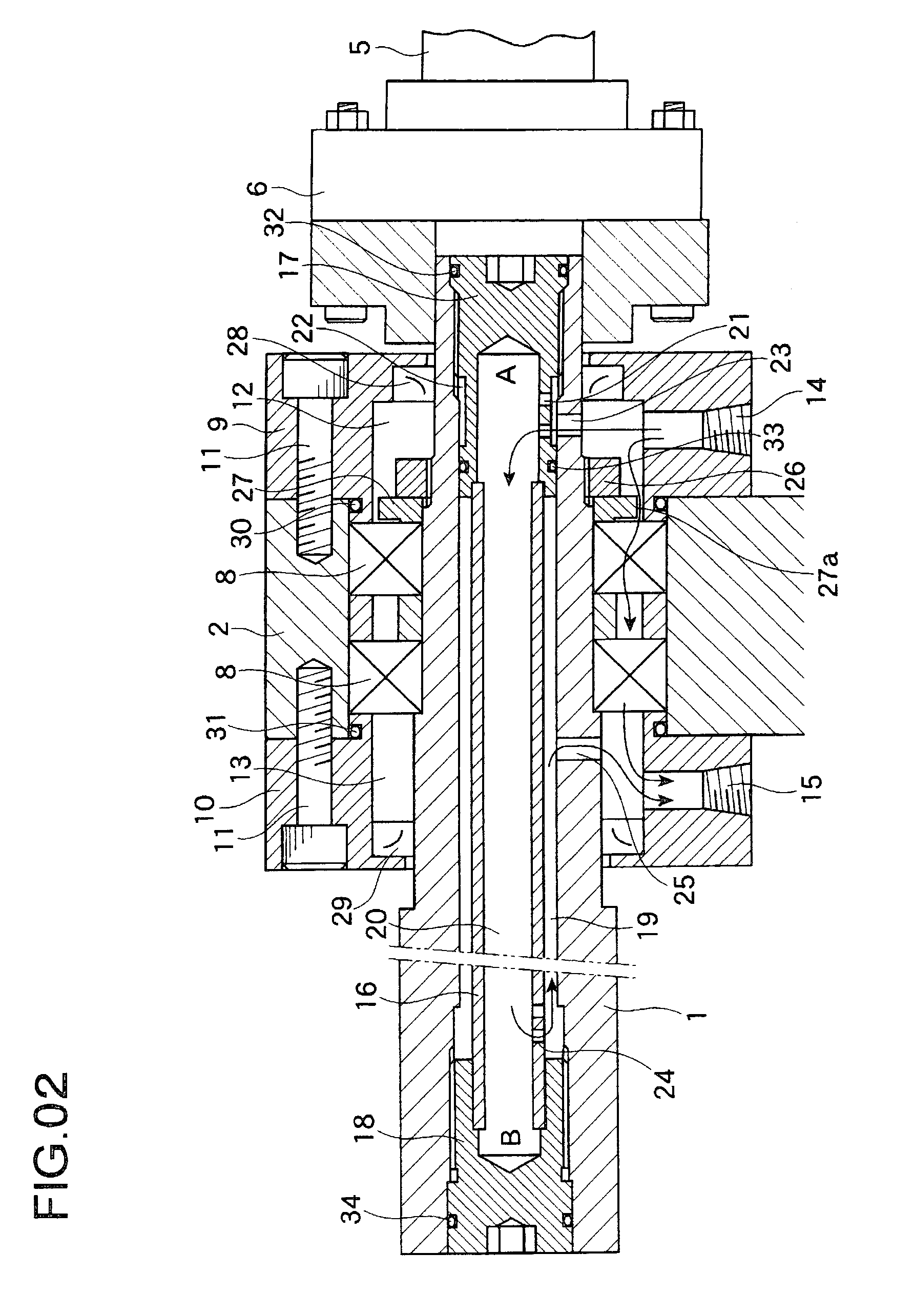
[0026]Embodiments of the invention are illustrated below based on the drawings. FIG. 1 is a schematic structural diagram of the feed shaft of a machine tool employing the cooling / lubricating device of the invention. FIG. 2 is a cross section schematically illustrating details of the feed shaft illustrated in FIG. 1. In the figures, the feed shaft (feed ball screw) 1 is rotatably supported by a support 2 fixed to one end. The other end is open, that is, unsupported. The intermediate portion of the feed shaft 1 is provided with a slide 3 that is driven by the feed shaft 1. The slide 3 may mean what is referred to as a table, saddle, ram, knee, tool rest, tool post, carriage, spindle head, or the like in machine tools.
[0027]The feed shaft 1 in this example is composed of a feed screw, such as a ball screw used in NC machine tools. As the structure and function are well-known, they will not be further elaborated. The slide 3 is, for example, a machining center table or the like. A nut 4...
PUM
 Abstract
Description
Claims
Application Information
 - R&D Engineer
- R&D Manager
- IP Professional
- Industry Leading Data Capabilities
- Powerful AI technology
- Patent DNA Extraction
Browse by: Latest US Patents, China's latest patents, Technical Efficacy Thesaurus, Application Domain, Technology Topic, Popular Technical Reports.
© 2024 PatSnap. All rights reserved.Legal|Privacy policy|Modern Slavery Act Transparency Statement|Sitemap|About US| Contact US: help@patsnap.com


