Slide Fastener and a Slider for a Slide Fastener

a slide fastener and slider technology, applied in the field of fluid-tight slide fasteners, can solve the problems of difficult opening/closing of the fastener and difficult cooling, and achieve the effects of reducing the thickness of the diamond, reducing the temperature profile and density of the slider, and significantly reducing the cooling step

Inactive Publication Date: 2009-09-17
RIRI
View PDF4 Cites 5 Cited by
  • Summary
  • Abstract
  • Description
  • Claims
  • Application Information

AI Technical Summary

Benefits of technology

[0019]An advantage of the invention is that the thickness of the diamond is reduced and made comparable with thickness of the other parts, namely blades and flanges. The cavity having sides parallel to faces of the diamond and then a cross-section corresponding to cross section of the diamond itself, in particular, allows to keep the thickness of the walls of the slider substantially constant.
[0020]Hence, the above drawbacks due to non-uniformity of the temperature profile and density of the slider, during the cooling step, are significantly reduced. It follows that the finished product is closer to the nominal dimensions and shape. In other words, the quality is improved and, in a production line, the number of sliders to be rejected is diminished. Another advantage is that the cooling time of the slider is reduced and a higher production rate can be reached.
[0021]These and further advantages of the invention will be more evident from the detailed description provided here below, given as indicative and not limiting example.

Problems solved by technology

A problem of fluid-tight fastener is that the top stop must necessarily have a seat or opening to receive the slider, when the slider reaches the top stop itself, being at the end of its stroke (i.e. full-closed slider); said seat or opening however may be a weak point from the point of view of fluid-tightness and hence it must be adequately sealed when the slider is closed.
Otherwise, the slider may be unable to guarantee the sealing at the region of the top stop, in case of excessive clearance between the slider and the top stop itself or, on the other hand, undesired interference between the slider and the top stop, namely between respective flanges and leg portions, may result in a difficult opening / closing of the fastener.
Similar drawbacks may be caused by a deviation from the design shape of the slider, e.g. concerning the curved profile of the flanges, the form of the diamond, and so on.
In die-cast and injection-molded sliders, the applicant has found that the above drawbacks may be caused by the shrinking of the slider during the cooling phase, especially due to fact that the diamond is a relatively thick part of the slider itself, namely thicker than other parts like blades and flanges.
It should also be noted that the diamond is the innermost part of the molding, hence the most difficult to cool down.

Method used


Image

  • Slide Fastener and a Slider for a Slide Fastener
  • Slide Fastener and a Slider for a Slide Fastener
  • Slide Fastener and a Slider for a Slide Fastener

Examples


Embodiment Construction

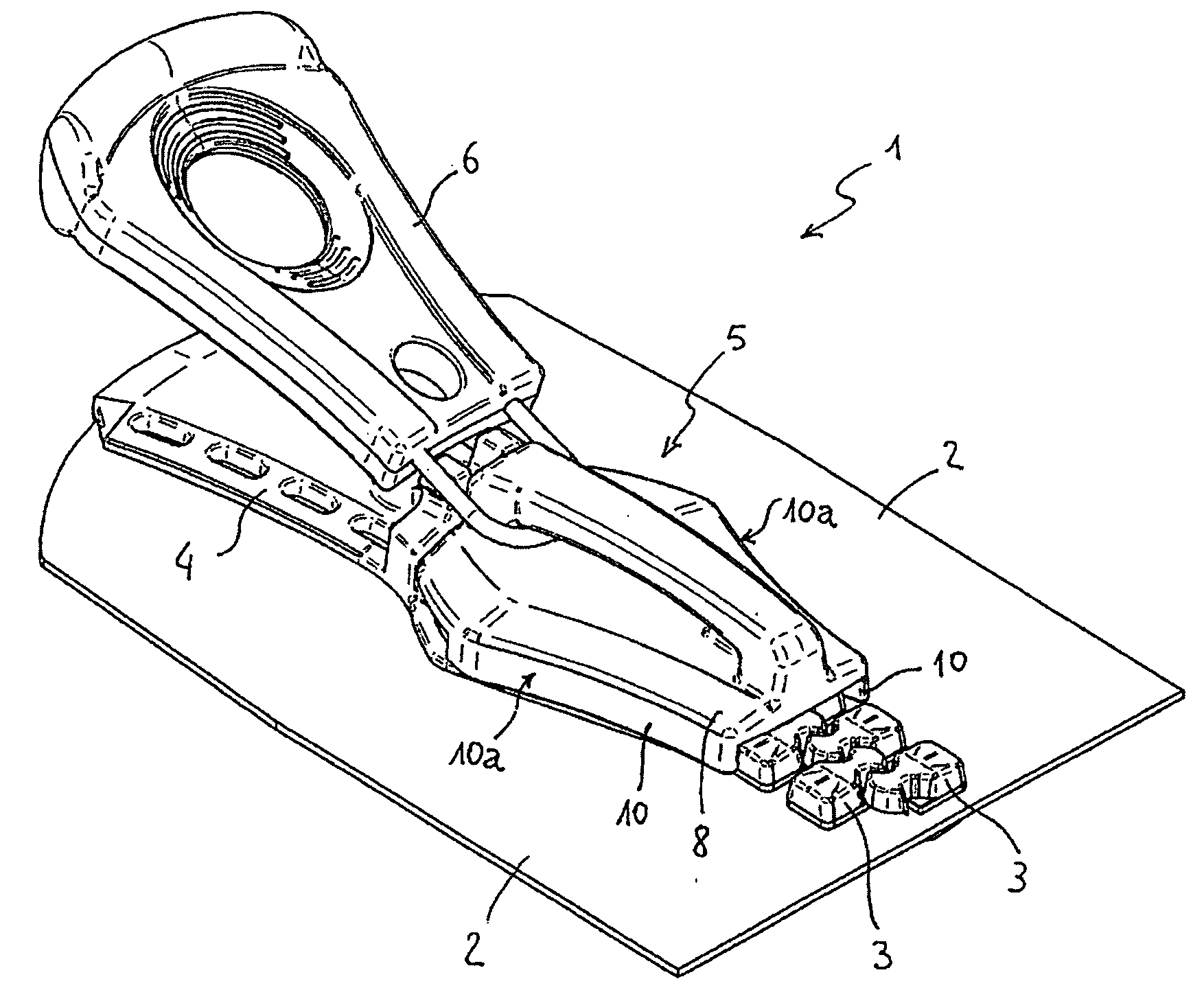
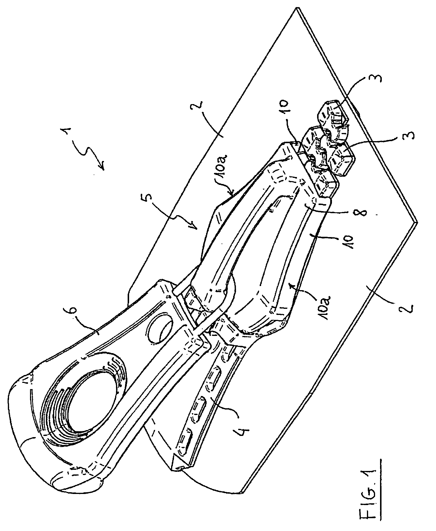
[0027]FIG. 1 shows a slide fastener 1, namely the top part thereof, in accordance with a an embodiment of the invention and comprising a pair of tapes 2, equipped with teeth 3, a top stop 4, and a slider 5 with a pull-tab or puller 6.

[0028]The slider 5 is movable in a sliding direction, parallel to tapes 2, up to a closing position where the slider 5 is accommodated into the top stop 4, and the fastener 1 is fully closed, i.e. all teeth 3 are engaged. Said closing position is shown in FIG. 1.

[0029]Details of tapes 2 an teeth 3 can be according to known art and are not discussed in detail. For example, in a fluid-tight sliding fastener 1, tapes 2 are made of a textile core layer fully coated on both sides by a suitable waterproof layer and teeth 3 are injection molded on tapes 2. The top stop 4 can also be injection-molded on tapes 2.

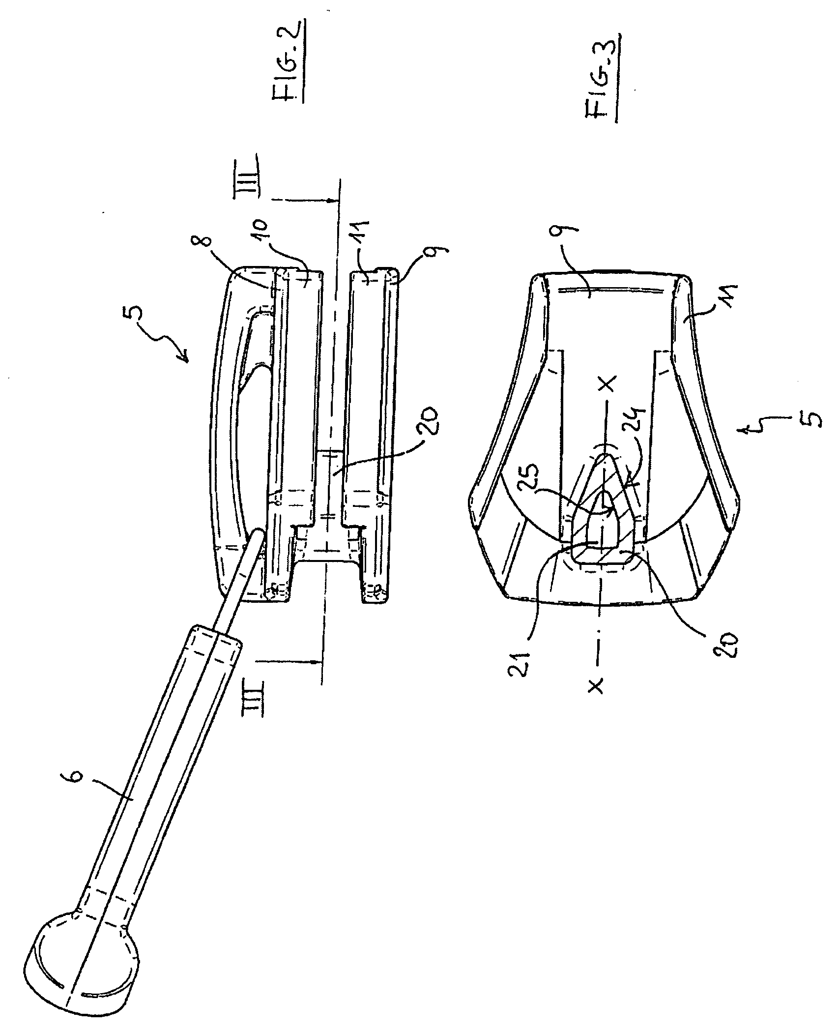
[0030]The slider 5 substantially comprises upper and lower blades 8, 9 with lateral flanges 10, 11 on both sides, and a diamond 20 connecting said upper...


PUM

PropertyMeasurementUnit
pressureaaaaaaaaaa
draft angleaaaaaaaaaa
thicknessaaaaaaaaaa

Abstract

A slide fastener (1) comprising a pair of tapes (2), carrying respective teeth (3), a top stop (4) and a die-cast or injection-molded slider (5), said slider (5) having a structure with an upper blade (8), a lower blade (9), lateral flanges (10, 11) and a diamond (20) connecting the upper and lower blades, wherein a cavity (21) is formed in said diamond (20).

Description

FIELD OF APPLICATION[0001]The present invention refers to a slide fastener and to a slider of a slide fastener. The invention relates in particular to fluid-tight slide fasteners and sliders thereof.PRIOR ART[0002]A slide fastener, in essential terms, comprises a pair of tapes bearing respective rows of teeth, top and bottom stops, and a slider for opening and closing the fastener by engaging and disengaging the teeth.[0003]Fluid-tight slide fasteners are slide fasteners adapted to securely prevent the passage of a liquid and / or gas, e.g. water and / or air. In some cases, a fluid-tight fastener must ensure fluid-tightness even under a significant pressure difference between the interior and the exterior, for example up to about 2 bars. Fluid-tight slide fasteners are realized for example with layered tapes made of a textile core with a waterproof coating layer and injection-molded teeth.[0004]The slider, according to known art, comprises upper and lower blades, lateral flanges and a ...

Claims


Application Information

Patent Timeline
Patent Type & Authority Applications(United States)
IPC IPC(8): A44B19/26B29D5/00
CPCA44B19/301Y10T29/49783Y10T24/2588A44B19/32
Inventor PEANO, ROBERTO
Owner RIRI
Why Eureka
Try Eureka