
Method for producing silver nanoparticles and conductive ink

a silver nanoparticle and conductive ink technology, applied in the field of producing metal nanoparticles, can solve the problems of limited mass production efficiency, low yield rate of metal nanoparticles by this existing method, and limitation of metal nanoparticles' yield rate, etc., to achieve high yield rate, simple process, and uniform size

Inactive Publication Date: 2009-09-10
SAMSUNG ELECTRO MECHANICS CO LTD
View PDF3 Cites 77 Cited by
  • Summary
  • Abstract
  • Description
  • Claims
  • Application Information

AI Technical Summary

Benefits of technology

[0008]The present invention provides a method of producing metal nanoparticles, not requiring high reaction temperature by using a copper compound as a reducing agent and having a high yield rate and uniform size achieved by a simple process. In addition, the present invention provides metal nanoparticles of several or several tens of nanometer size and a high conductive ink including the metal nanoparticles thus obtained.

Problems solved by technology

However, the production of metal nanoparticles by this existing method provides a very low yield rate, as it is limited by the concentration of the metal compound solution.
Thus, there is a limit also on the yield of metal nanoparticles, and to obtain metal nanoparticles of uniform size in quantities of several grams, 1000 liters or more of functional group are needed.
This represents a limitation to efficient mass production.
Moreover, the phase transfer method necessarily requires a phase transfer, which is a cause of increased production costs.

Method used


Image

  • Method for producing silver nanoparticles and conductive ink
  • Method for producing silver nanoparticles and conductive ink
  • Method for producing silver nanoparticles and conductive ink

Examples


example 1

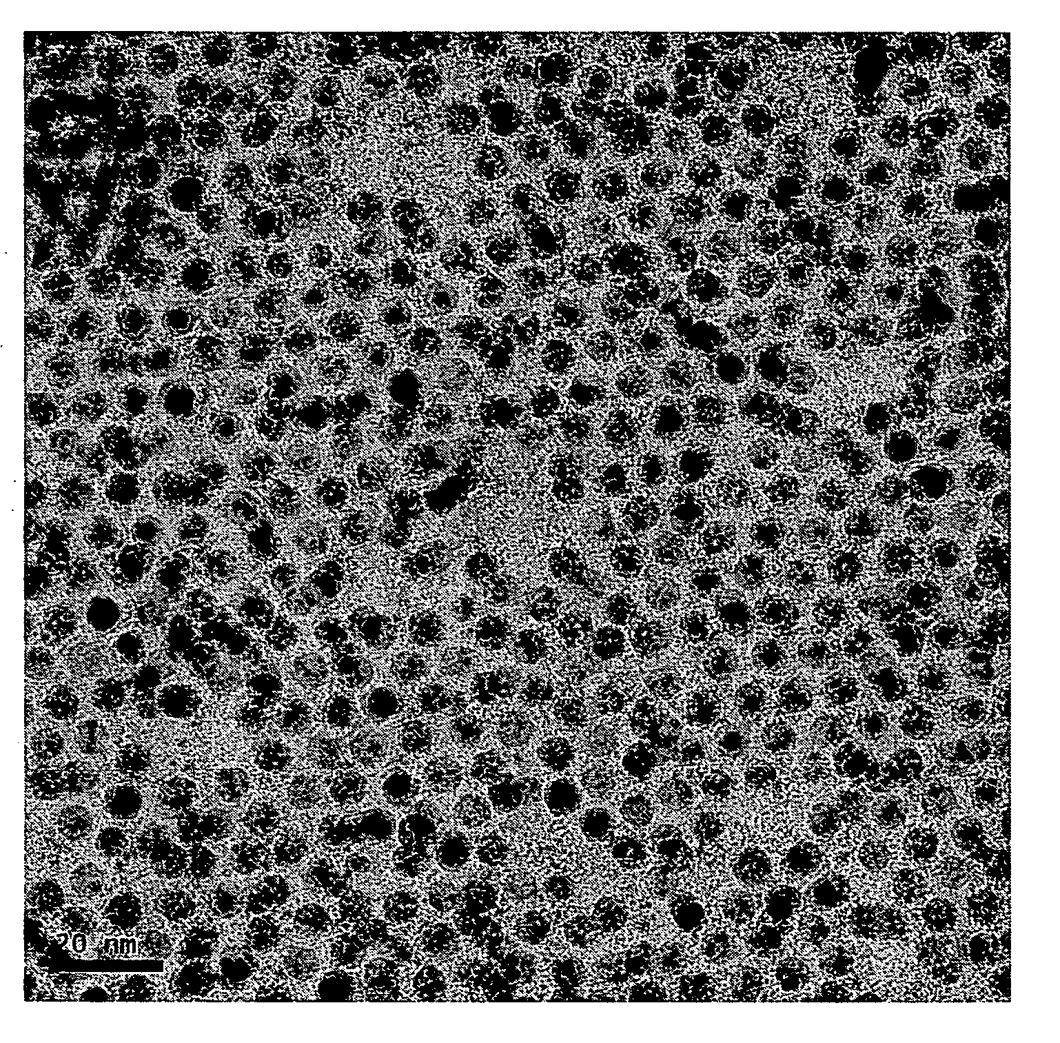
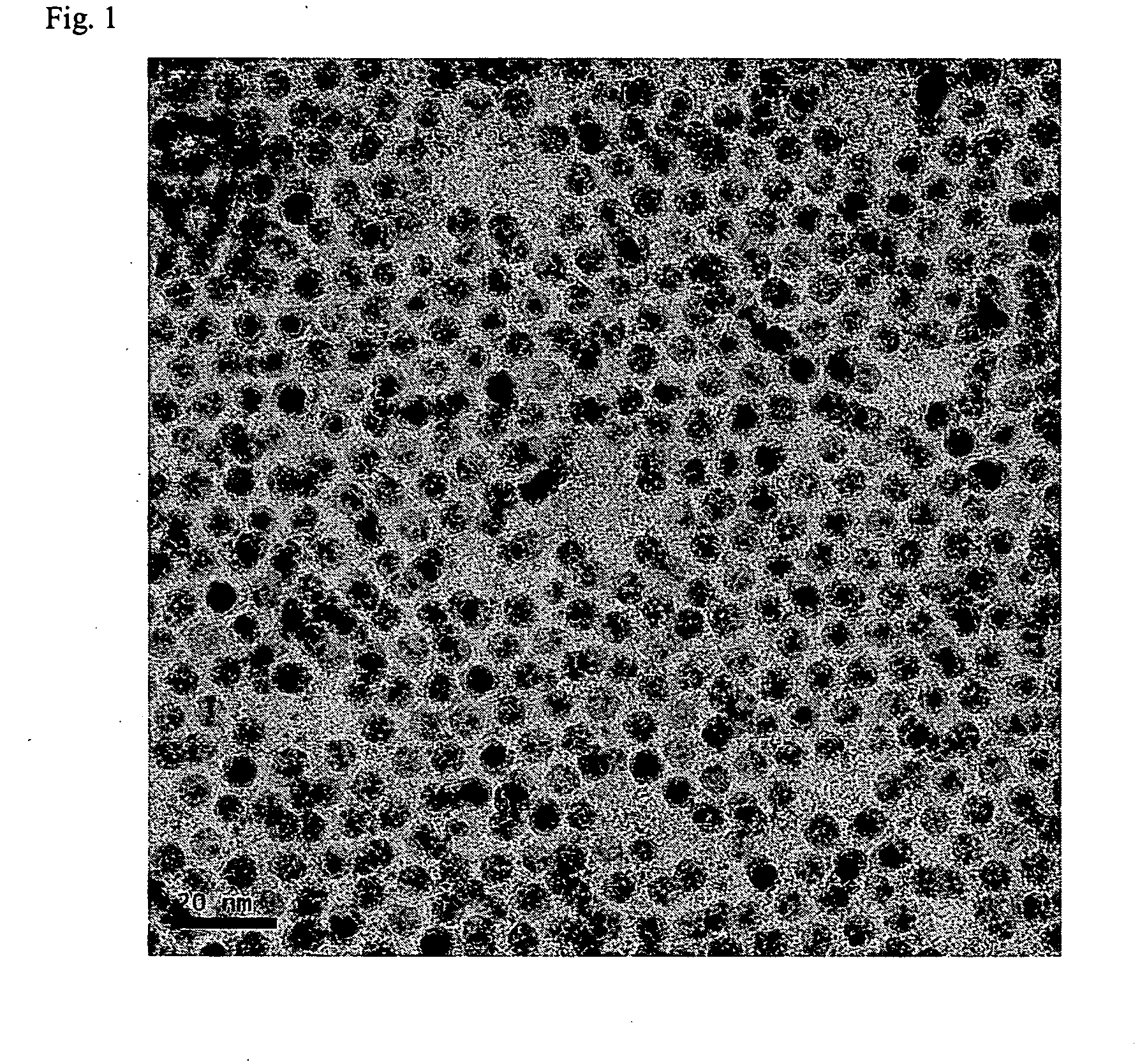
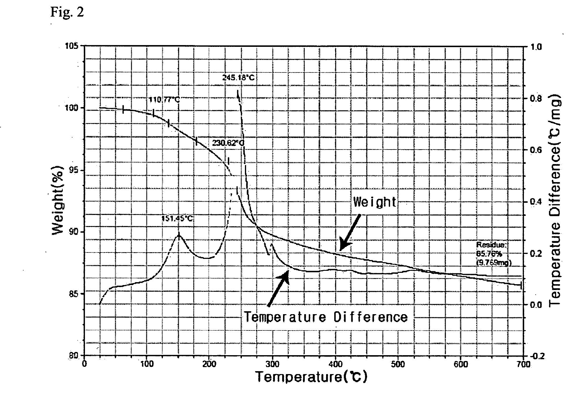
[0046]170 g of AgNO3 and 20 g of copper (II) acetoacetate (Cu(acac)2) compound were mixed to 300 g of toluene solvent and then 100 g of butylamine was further added and stirred. 50 g of palmitic acid was added to this mixed solution. The reaction mixture was heated to 110° C. and then sustained by stirring for 2 hours and cooled to room temperature (28° C.). Ag nanoparticles thus formed were added to methanol and centrifuged to precipitate and the precipitates, Ag nanoparticles, were separated out. As shown in FIG. 1, 90 g of metal nanoparticles that have uniform size distribution of 4 nm were obtained. As illustrated in FIG. 2, the result of TGA analysis shows that Ag content by percentage is 85 wt %. When Ag nanoparticles thus retrieved were re-dispersed in an organic solvent, high dispersion stability was observed, re-dispersion yield rate was also high.

example 2

[0047]170 g of AgNO3 and 20 g of copper (II) acetoacetate (Cu(acac)2) compound were mixed to 300 g of toluene solvent and then 100 g of butylamine was further added and stirred. 50 g of oleylamine was added to this mixed solution, and these mixed compounds were heated to 110° C. and then sustained by stirring for 1 hour and cooled to room temperature (28° C.). Ag nanoparticles thus formed were added to methanol and centrifuged to precipitate and the precipitates, Ag nanoparticles, were separated out. As shown in FIG. 3, 90 g of metal nanoparticles that have uniform size distribution of 5 nm were obtained.


PUM

PropertyMeasurementUnit
Temperatureaaaaaaaaaa
Sizeaaaaaaaaaa
Electrical conductivityaaaaaaaaaa

Abstract

A method of producing metal nanoparticles in a high yield rate and uniform shape and size, which is thus suitable for mass production. In addition, metal nanoparticles are provided that have superior dispersion stability when re-dispersed in various organic solvents, which thus suitable for use as a conductive ink having high conductivity. The method of producing nanoparticles includes mixing a metal precursor with a copper compound to a hydrocarbon based solvent, mixing an amine-based compound to the mixed solution of the metal precursor with copper compound and hydrocarbon based solvent, and mixing a compound including one or more atoms having at least one lone pair, selected from a group consisting of nitrogen, oxygen, sulfur and phosphorous to the mixed solution of the amine-based compound, metal precursor with a copper compound and hydrocarbon based solvent.

Description

CROSS-REFERENCE TO RELATED APPLICATIONS[0001]This application claims the benefit of Korean Patent Application No. 10-2005-0072478 filed on Aug. 8, 2005, with the Korea Intellectual Property Office, the contents of which are incorporated here by reference in their entirety.BACKGROUND[0002]1. Technical Field[0003]The present invention relates to a method of producing metal nanoparticles, in particular, to a method of producing metal nanoparticles with the solution method.[0004]2. Description of the Related Art[0005]Major ways to produce metal nanoparticles are the vapor-phase method and the solution (colloid) method. Since the vapor-phase method which uses plasma or gas evaporation requires highly expensive equipments, the solution method which is easy for the production is generally used.[0006]A method of producing metal nanoparticles by the solution method up to now is to dissociate a metal compound in a hydrophilic solvent and then apply a reducing agent or a surfactant to produce ...

Claims


Application Information

Patent Timeline
IPC IPC(8): C09D11/00B22F9/20B32B15/02B22F1/00B22F1/02B22F9/24B82B1/00B82B3/00B82Y20/00B82Y30/00B82Y40/00C09C1/62C09C3/08C09D7/62C09D11/322C09D11/38C09D11/52H01B1/22
CPCB22F9/24C08K3/08C09D7/1225C09D7/1266C09D11/38Y10T428/2982H01B1/22B22F2998/00C09D11/52Y10S977/896B22F1/0018C09D7/62C09D7/67B82B3/00
Inventor JUN, BYUNG-HOLEE, KWI-JONGCHO, HYE-JINJOUNG, JAE-WOO
Owner SAMSUNG ELECTRO MECHANICS CO LTD
Learn More