Solid-state image pickup device and electronic apparatus including same

Inactive Publication Date: 2009-09-03
SHARP KK
View PDF2 Cites 33 Cited by
  • Summary
  • Abstract
  • Description
  • Claims
  • Application Information

AI Technical Summary

Benefits of technology

[0011]The present invention has been accomplished in view of the above problem. It is an object of the present invention to provide a solid-state image pickup device capable of preventing contamination by dirt into a light path so as to reduce imaging defects, and to provide an electronic apparatus including the solid-state image pickup device.
[0013]According to the above invention, the lens unit is held on the external side part of the holding section (outside the lens holder). This keeps an area where the lens unit and the lens holder are in contact with each other, away from the solid-state image pickup element. This in turn prevents contamination by dirt into a light path, the dirt being caused by friction between the lens unit and the lens holder (the first internal screw section of the lens unit and the first external screw section of the holding section). As a result, it is possible to reduce imaging defects caused by such dirt.
[0015]According to the above invention, the lens unit includes a lens, a lens barrel, and a macro ring. In other words, the solid-state image pickup device has a macro photography function. In this solid-state image pickup device having the macro photography function, the first internal screw section is formed on the internal side of the macro ring. This allows the macro ring to be held on the external side part of the holding section (outside the lens holder). This in turn keeps an area where the macro ring and the lens holder are in contact with each other, away from the solid-state image pickup element. This prevents contamination by dirt into the light path, the dirt being caused by friction between the macro ring and the lens holder (i.e., between the first internal screw section of the macro ring and the first external screw section of the holding section). As a result, it is possible to reduce imaging defects caused by such dirt in the solid-state image pickup device having the macro photography function.
[0016]In order to attain the above object, an electronic apparatus of the present invention includes the solid-state image pickup device. This allows provision of an electronic apparatus capable of preventing contamination by dirt into the light path so as to reduce imaging defects.

Problems solved by technology

However, the arrangement of Patent Document 1 poses a problem that imaging defects are caused by contamination by dirt in a light path.
This causes a black dot or stain to be reflected in an outputted image, thereby leading to a decrease in yield and reliability of the camera module 600.
This causes direct contamination by the dirt caused as above into the light path, thereby causing an imaging defect.

Method used


Image

  • Solid-state image pickup device and electronic apparatus including same
  • Solid-state image pickup device and electronic apparatus including same
  • Solid-state image pickup device and electronic apparatus including same

Examples


first embodiment

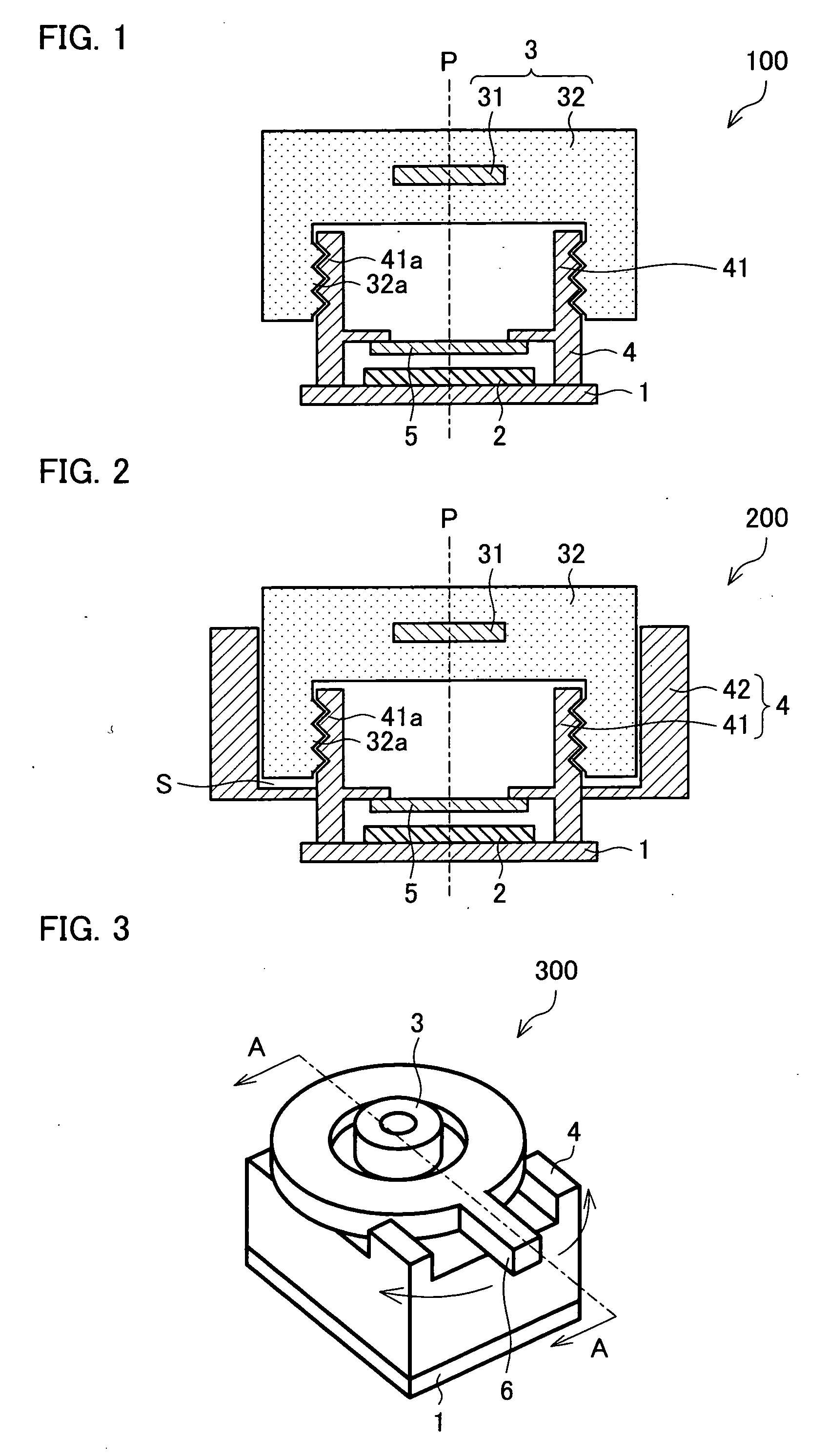
[0028]FIG. 1 is a cross-sectional view illustrating a camera module 100 according to a first embodiment. As illustrated in FIG. 1, the camera module 100 includes a circuit board 1, and a solid-state image pickup element 2 mounted on the circuit board 1. The camera module 100 further includes a lens unit 3, and a lens holder 4 which contains the solid-state image pickup element 2 and which holds the lens unit 3. The camera module 100 also includes a light-transmitting member 5 which is held by the lens holder 4 and which is provided so as to face the solid-state image pickup element 2. Note that, for convenience of explanation, “on a circuit board 1 side (i.e., closer to the circuit board 1)” is referred to as “downward”, whereas “on a light-transmitting member 5 side (i.e., on a lens unit 3 side, or farther from the circuit board 1)” is referred to as “upward.”

[0029]The circuit board 1, which receives an electric signal from the solid-state image pickup element 2, is a board having ...

second embodiment

[0046]FIG. 2 is a cross-sectional view illustrating a camera module 200 according to a second embodiment. It should be noted that members in the second embodiment which are same as or similar to those used in the first embodiment are assigned the same reference numerals, and that the description of the members is omitted.

[0047]As illustrated in FIG. 2, the camera module 200 of the present embodiment has an arrangement substantially similar to that of the camera module 100 of the first embodiment. The difference between the two camera modules 100 and 200 lies in the shape of a lens holder 4.

[0048]Specifically, in addition to the arrangement of the lens holder 4 of the camera module 100, the lens holder 4 of the camera module 200 includes a surrounding section 42 which surrounds a bottom part and an outer periphery part of the lens barrel 32. The surrounding section 42 is provided so as to extend from the external side surface of the holding section 41 (i.e., from the surface on which...

third embodiment

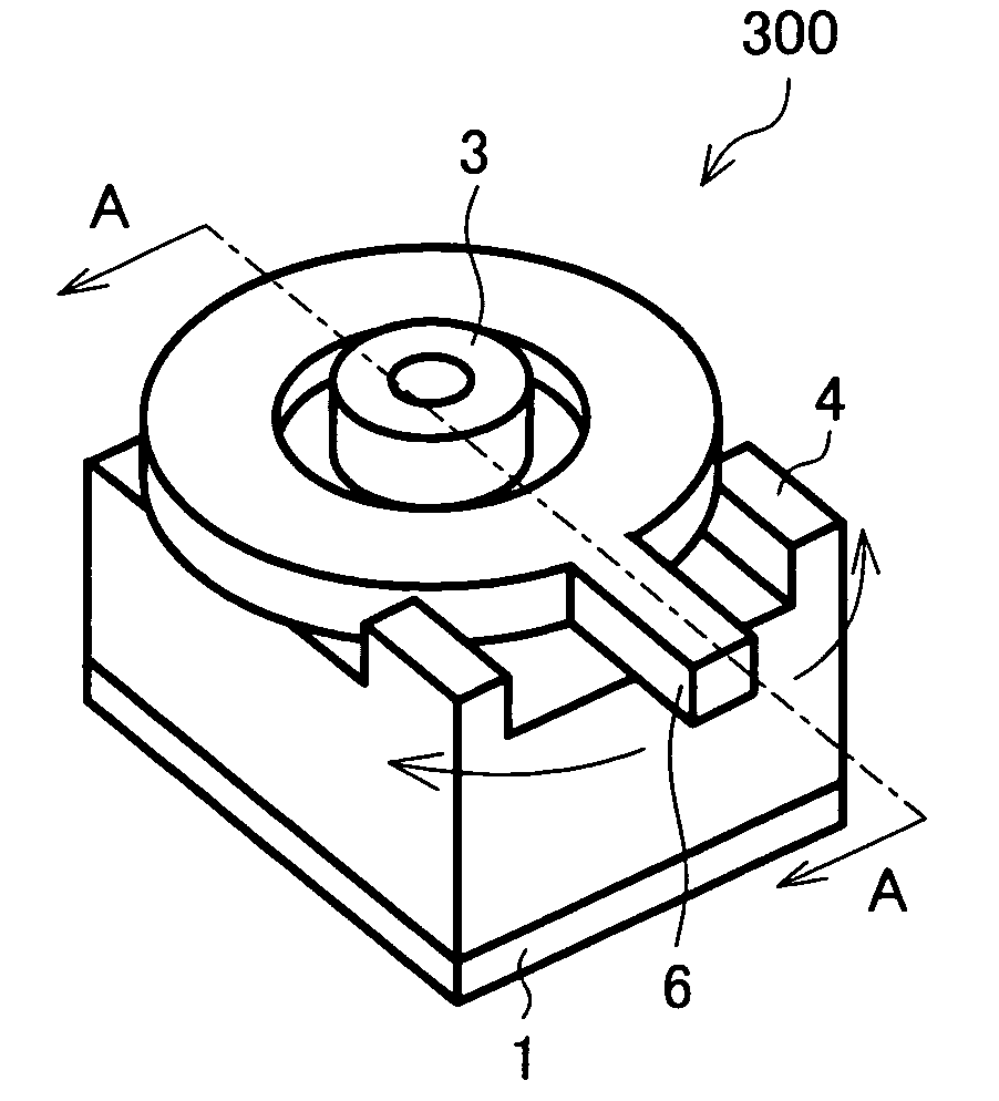
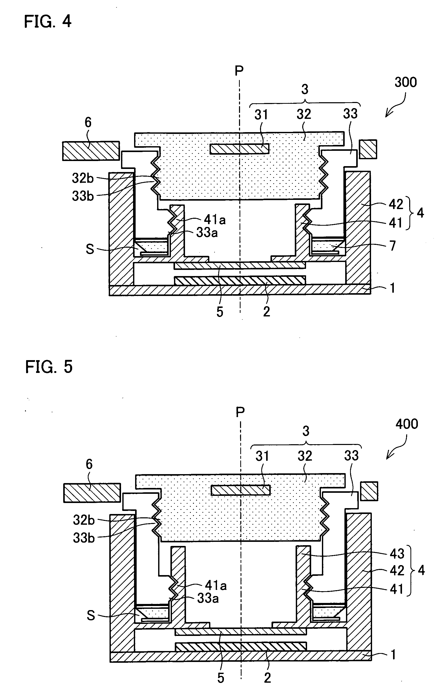
[0062]FIG. 3 is a perspective view illustrating an outline of a camera module according to the present embodiment. FIG. 4 is a cross-sectional view, taken on A-A line of FIG. 3, illustrating the camera module 300 of FIG. 3. It should be noted that members in the third embodiment which are same as or similar to those illustrated in FIGS. 1 and 2 used in the first and second embodiments, respectively, are assigned the same reference numerals, and that the description of the members is omitted.

[0063]As illustrated in FIG. 4, the camera module 300 of the present embodiment has an arrangement substantially similar to that of the camera module 200 of the second embodiment. The camera module 300 is different from the camera module 200 in that: the camera module 300 has a macro photography function; the lens holder 4 includes a surrounding section 42 in addition to the holding section 41; and the camera module 300 includes a tension ring 7.

[0064]Specifically, as illustrated in FIG. 3, the c...


PUM


Abstract

A camera module 100 of the present invention is arranged such that a lens barrel 32 is provided with an internal screw thread 32a on its internal side, and that a holding section 41, which is a portion of a lens holder 4, the portion holding a lens unit 3, is provided with an external screw thread 41a on its external side, the external screw thread 41a being engaged with the internal screw thread 32a. As a result, it is possible to provide the camera module 100 capable of preventing contamination by dirt into a light path and thereby reducing imaging defects.

Description

[0001]This Nonprovisional application claims priority under U.S.C. §119(a) on Patent Application No. 048641 / 2008 filed in Japan on Feb. 28, 2002, the entire contents of which are hereby incorporated by reference.FIELD OF THE INVENTION[0002]The present invention relates to a solid-state image pickup device capable of preventing adherence of dirt in a light path so as to reduce imaging defects, and to an electronic apparatus including the solid-state image pickup device.BACKGROUND OF THE INVENTION[0003]A portable terminal (electronic apparatus) such as a camera-equipped portable phone includes a camera module (solid-state image pickup device). Many camera-equipped portable phones have a closeup mode (macro photography mode) used to photograph a flower and the like in a closeup manner, in addition to a normal photography mode used to photograph a person, scenery and the like.[0004]Patent Document 1, for example, discloses a camera module having a macro photography function. FIG. 7 is a...

Claims


Application Information

Patent Timeline
IPC IPC(8): H04N5/225
CPCG02B7/025H04N5/2171G02B7/022H04N5/2257H04N5/2254H01L27/14618H04N23/811H04N23/52H04N23/57H04N23/55
Inventor HIGUCHI, MASATOMO
Owner SHARP KK
Why Eureka
Try Eureka