One-piece non-contaminating milk or food container seal and seal removal system

Inactive Publication Date: 2011-09-29
MC CLELLAN W THOMAS
View PDF17 Cites 8 Cited by
  • Summary
  • Abstract
  • Description
  • Claims
  • Application Information

AI Technical Summary

Benefits of technology

[0018]In accordance with an added feature of the invention, the tab is an extraction ring attached to the seal. Such a ring is quite easy to be hooked by a finger for removal.
[0019]In accordance with an additional feature of the invention, the seal is cup-shaped. The concave shape of the seal facilitates grasping and extraction of the tab or ring.
[0021]In accordance with yet a further feature of the invention, the outer periphery of the seal is “thin link” fused to or cast with the top edge of the channel or pouring spout. This line of weakness extends circumferentially of the receptacle mouth or spout. This separation line facilitates tearing of the seal from the channel or pouring spout.
[0023]In accordance with yet an additional feature of the invention, the seal is formed of flexible plastic, which makes it easy to remove.
[0024]In accordance with again another feature of the invention, the seal, said tab and an inner surface of said closure are all in contact with and do not extend above said top edge. This feature is provided in order to prevent contamination before and during said removal of said seal.
[0027]The new seal and seal removal system according to the invention controls and maintains a sterile technique for seal breaking and seal removal. This simple, easy to use, and failsafe system, even when operated by the untrained consumer, keeps contamination totally contained within the seal and discards bacteria within the seal. The entrance channel or pouring spout is never touched, and sterile technique is maintained before, during and after opening the seal. The milk or food is protected.

Problems solved by technology

The placement of the seal at the very top of the channel or pouring spout means that the entire inner surface of the channel or pouring spout is inaccessible.

Method used


Image

  • One-piece non-contaminating milk or food container seal and seal removal system
  • One-piece non-contaminating milk or food container seal and seal removal system
  • One-piece non-contaminating milk or food container seal and seal removal system

Examples


Embodiment Construction

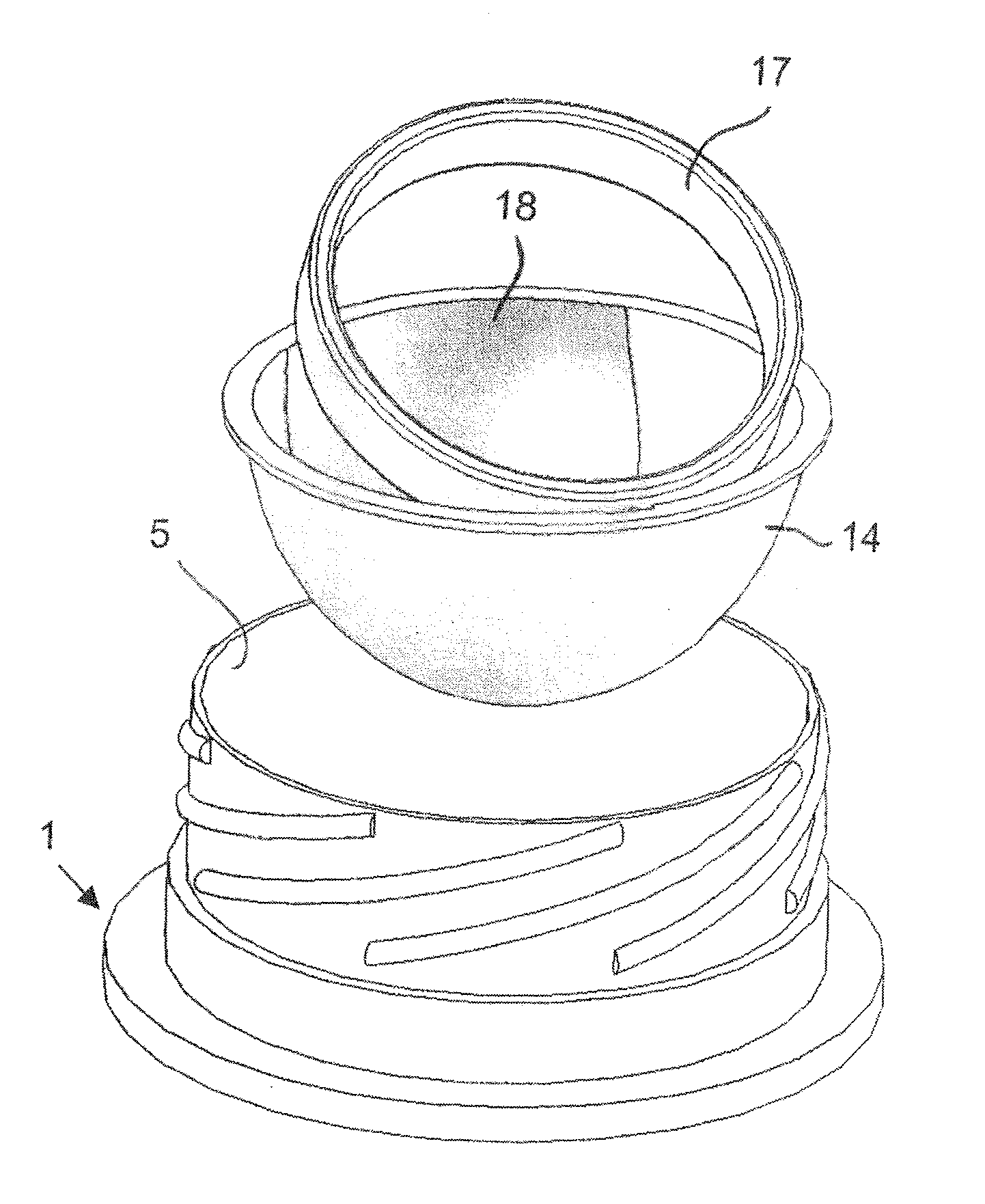
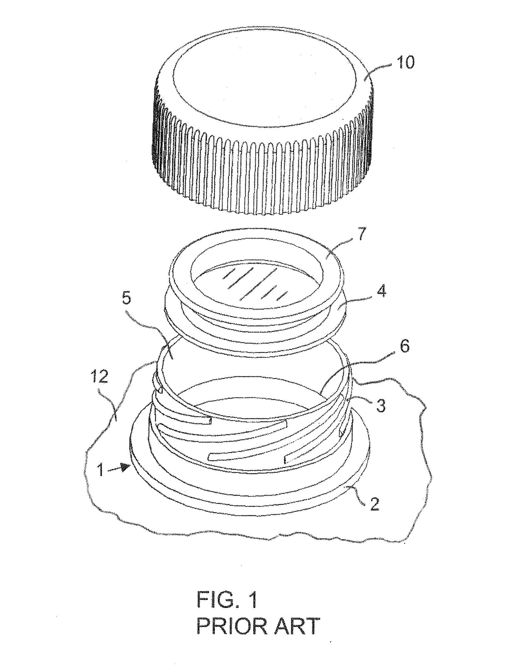
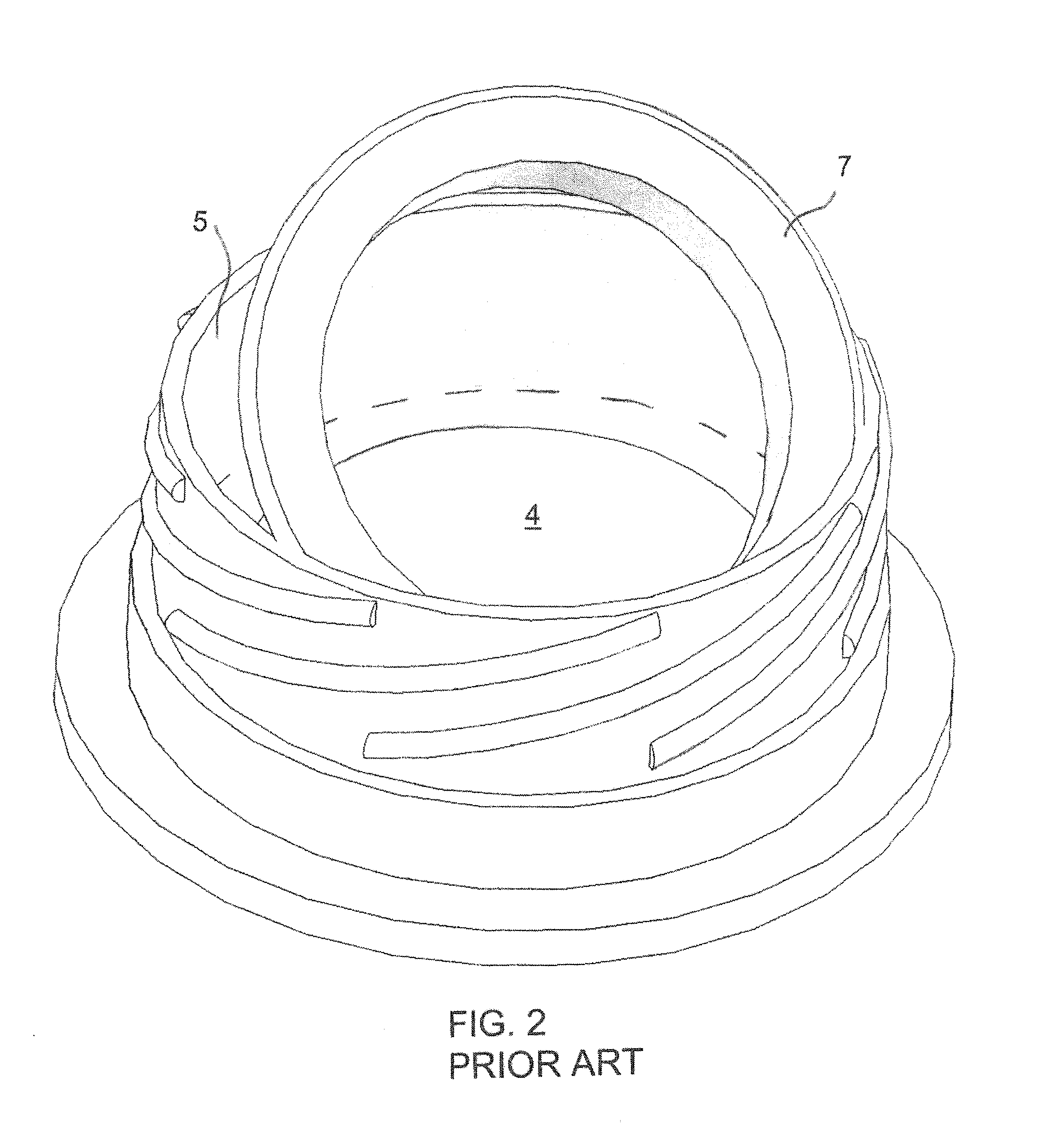
[0044]Referring now to the figures of the drawings in detail and first, particularly, to FIG. 1 thereof, there is seen a conventional entrance channel or pouring spout 1, which is attached at a bottom rim 2 thereof to an opening at the top of a milk or food container 12. A cap 10 has a non-illustrated internal thread which is to be screwed onto an external thread 3 of the channel or pouring spout 1. A prior art milk or food container seal and seal removal system includes a disk-shaped seal 4 having an outer periphery which is connected to an inner surface 5 of the channel or pouring spout 1 at a level 6. More specifically, the seal 4 is fused or cast onto the lower one-quarter of the channel or pouring spout 1. An extraction ring 7 is connected to the seal 4. The ring 7 is hooked by the finger for tearing and extracting the seal 4 from the channel or pouring spout 1, thus breaking the sterile seal of the container.

[0045]FIG. 2 shows the seal 4, the ring 7 and the channel or pouring ...


PUM


Abstract

A one-piece non-contaminating milk or food container seal and seal removal system includes a channel or pouring spout to be connected to a food container. The spout has an inner surface to be contacted by contents of the container and the inner surface has a top edge. A seal prevents human contact with the inner surface of the channel or pouring spout. The seal has an outer periphery frangibly connected to the top edge. A tab permits unbroken, intact manual removal of the seal with one finger. A removable closure for the channel or pouring spout contacts the top edge before removal of the seal and after replacement of the removable closure. The tab does not extend above the top edge before removal of the closure and the seal. The channel or pouring spout, the seal and part of the tab are formed in one piece at the top edge.

Description

CROSS-REFERENCE TO RELATED APPLICATION[0001]This is a Continuation-In-Part, under 35 U.S.C. §120, of copending application Ser. No. 11 / 242,765, filed Oct. 4, 2005.BACKGROUND OF THE INVENTION[0002]1. Field of the Invention[0003]The present invention relates to one-a piece, non-contaminating milk or food container seal and a seal removal system.[0004]2. Description of the Related Art[0005]Presently many containers, cardboard and plastic milk containers in particular, have a sealing system which requires the user to insert a finger down “inside” the neck of the entrance channel or pouring spout and hook onto a loop for traction, to break a container seal. The seal is then discarded and the cap reapplied.[0006]The damage, however, has already been done. The same fingers used the bathroom, wiped the nose, shook hands or handled money. Those contaminated fingers have now touched the “inner” surface of the milk or food container entrance channel or pouring spout.[0007]A contaminated finger...

Claims


Application Information

Patent Timeline
IPC IPC(8): B65D51/20
CPCB65D51/18
Inventor MC CLELLAN, W. THOMAS
Owner MC CLELLAN W THOMAS
Why Eureka
Try Eureka