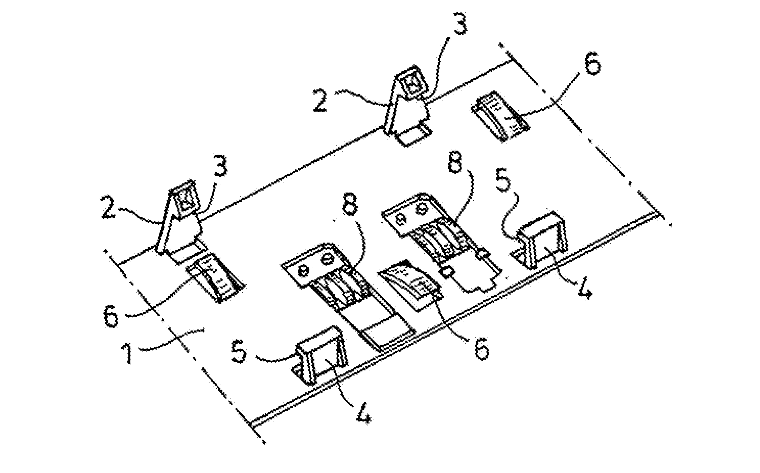
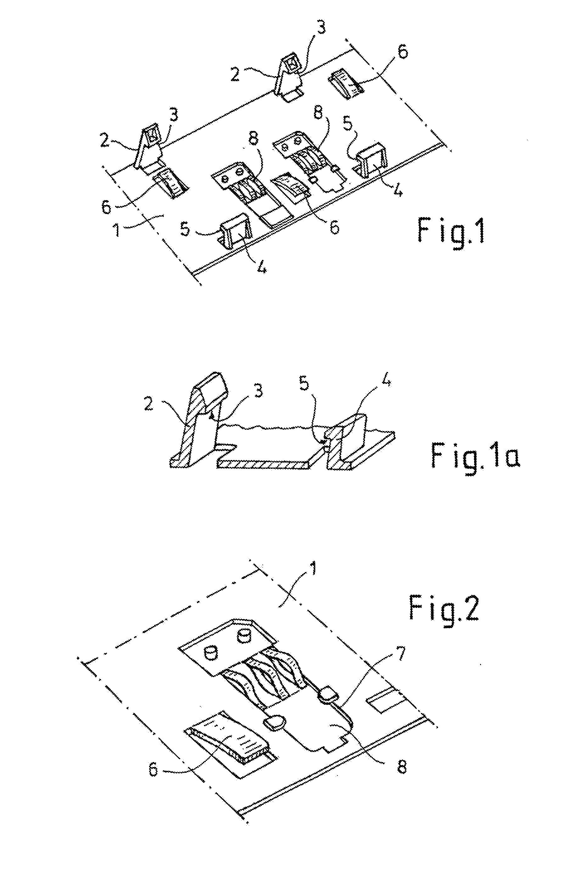
[0006]According to the invention, provision is made for the support to be generally planar and to have locking means as well as spring means cooperating therewith in order to fix the circuit board on the support as well as at least one cutout for holding a contact for establishing electrical contact between a contact surface of the circuit board and a corresponding contact surface on the vehicle part, in particular a vehicle panel. Due to the planar structure of the support (support plate), the required rigidity and stability of the support and the circuit board accommodated therein are improved because the support may be fastened, in particular adhered, to the vehicle part over a large area. The locking means as well as the spring means cooperating therewith have the
advantage that the circuit board may be fixed on the support quickly and simply in a position relative to the support that may be predetermined. The locking means allow the circuit board to be held at a maximum spacing from the support, while the spring means cooperating with the locking means allow the minimum spacing to be set. Overall, therefore, the interaction between the locking means and the spring means causes the circuit board to sit (“hover”) at a spacing from the support that may be predetermined, and the spring means protect the circuit board from vibration during operation of the vehicle. In addition, the spring means allow compensation for play, which is advantageous in compensating for temperature fluctuations or tolerances.
[0007]Another particularly important aspect of the invention is the at least one cutout (as a rule, several cutouts) for holding a contact for the purpose of establishing electrical contact between a contact surface of the circuit board and a corresponding contact surface on the vehicle part. In this manner, a contact with a corresponding structure may be fixed on the support such that
soldering a contact with a complex structure onto the lower face of the circuit board may be omitted. This also eliminates the danger that a contact soldered there may be bent or even broken off. The contacts fixed on the support, which may be installed even before mounting the support, offer the
advantage that they reliably create contact between the contact surfaces of the circuit board and the corresponding contact surfaces on the vehicle part and are no longer components of the circuit board, but rather of the support, whereby storage, transportation, and installation of the support as well as of the electronic device with its circuit board are considerably simplified and less complicated. Here, it is particularly possible to achieve an increase in the lot size per unit of volume, which reduces
transportation capacity, which in turn contributes to
environmental protection. In addition to simplified transportation, simpler handling, and improved protection of contacts, it is no longer necessary to fit the circuit board with spring-like contacts, particularly because the
soldering on the lower face of the circuit board is omitted as well, such thermal stress to the contacts during
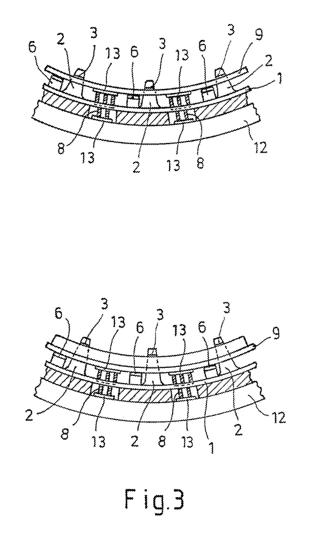
soldering is also unnecessary. Additional advantages may be seen in the fact that all types of geometric shapes of contacts and contact materials may be used. Particularly preferred are blade-shaped contacts having one attachment end for anchoring them to the support and one free end such that, if placed under a load, they are able to move axially out of the direction of the vehicle part or out of the direction of the circuit board, such that damage to the contact is prevented in this manner as well. Moreover, the
advantage of
cost savings in case of replacement should be mentioned as well because, if the circuit board is replaced, new contacts are unnecessary. It is also advantageous that replacement of the contacts is possible even when the support is adhered to the vehicle part and installation (and, if necessary, removal) of the contacts may be automated. By virtue of the blade-shaped contact springs, although other structures are conceivable as well, the long spring path allows a secure contact and its closed form (arcuate toward the contact surfaces) provides
toughness when handled. Moreover, a contact spring of this type may be produced in a more cost-effective manner because no substantial bending operations are required (fewer bending stations in the tool, the tool becomes considerably lighter and cheaper, a higher number of strokes is possible, which leads to lower process costs. There is also less use of material because virtually no waste occurs and a significantly thinner band may be used, resulting in further savings in weight and material).
[0009]In a further development of the invention, the support and / or the housing is structured for shielding the circuit electronic device from the sun or disruptive
radiation. By using appropriate materials (for example, for the support, a plastic to which
electrically conductive materials have been added or that has an
electrically conductive coating, like the housing, which may alternatively be made entirely of
metal), disruptive
radiation is prevented from disrupting operation by shining onto the electrical device. This also prevents the electronic device from emitting disruptive
radiation, in particular electromagnetic
waves, that could reach an
interior space in the vehicle.
[0010]In order to improve the cost situation and simplify mounting of the support, the support is made of a plastic that is processed in an injection-molding process. After production of the support, an
adhesive is applied to the lower face of the support facing the vehicle part, and in a particularly preferred embodiment the
adhesive is a double-sided
adhesive film provided with a protective before the support is mounted, which film may be removed so that the support may be adhered to the vehicle part. As an alternative, however, it is also conceivable to use other adhesion processes that meet the requirements for application in vehicles, in particular light- and temperature-resistance while providing the necessary contact forces due to the high degree of vibration during operation of the vehicle.
