
Fiber lens with fresnel zone plate lens and method for producing the same

a fiber lens and fresnel technology, applied in the field of optical devices, can solve the problems of difficult installation of optical couplers, short working distance, and increase in the overall size of optical coupling systems, and achieve the effect of easy assembly and manufacturing in miniatur

Inactive Publication Date: 2009-08-13
GWANGJU INST OF SCI & TECH
View PDF9 Cites 19 Cited by
  • Summary
  • Abstract
  • Description
  • Claims
  • Application Information

AI Technical Summary

Benefits of technology

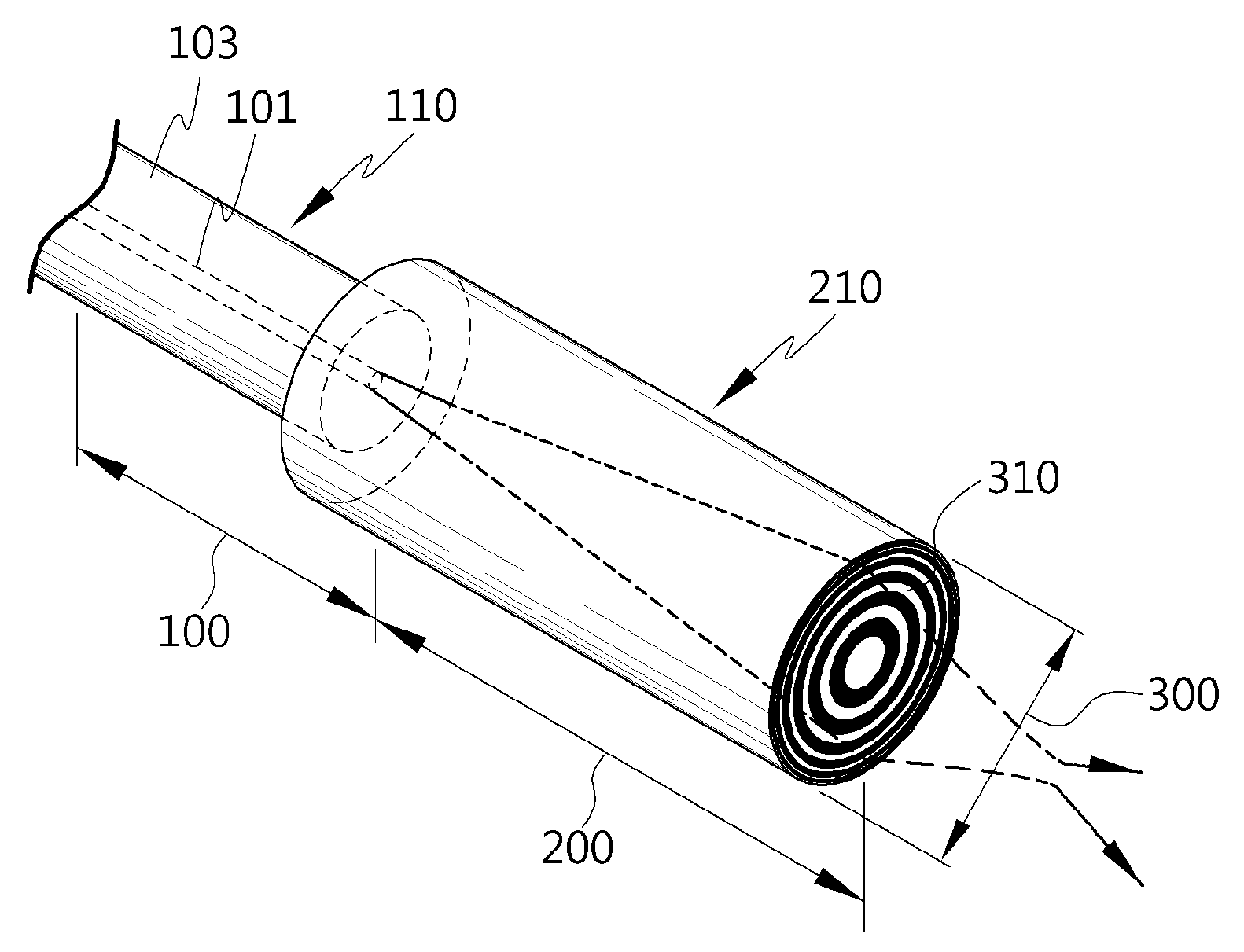
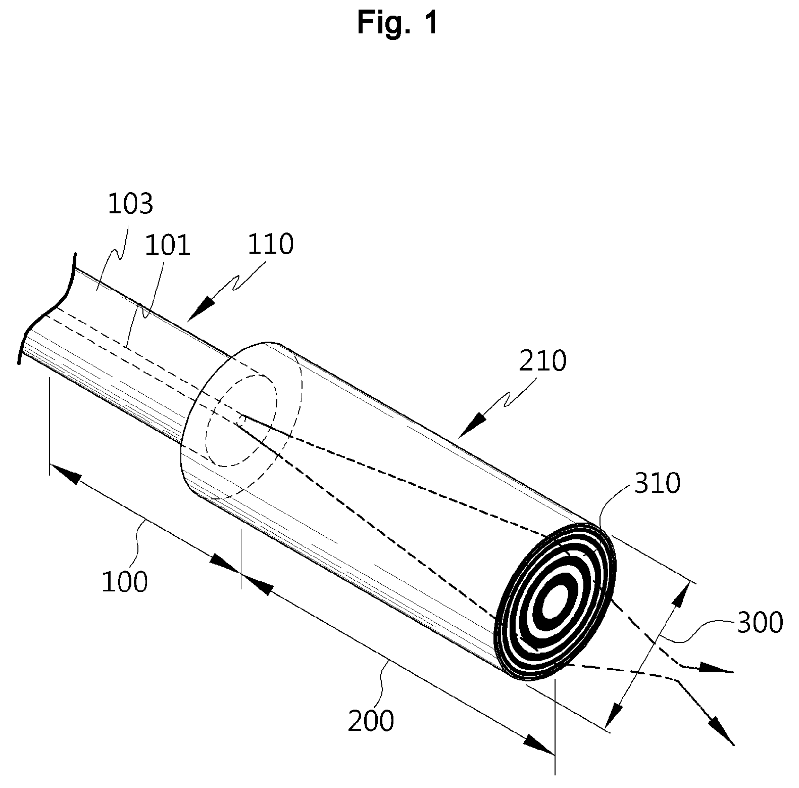
[0010]The present invention is directed to a Fresnel lens-integrated optical fiber that can be easily arranged and manufactured in miniature.
[0011]The present invention is also directed to a method of fabricating a Fresnel lens-integrated optical fiber that can be easily arranged, manufactured in miniature, and manufactured easily.

Problems solved by technology

However, in the method of fabricating an optical fiber lens by processing a longitudinal section of a single mode optical fiber, since a lens function is exhibited only in a region corresponding to a core diameter of the single mode optical fiber (for example, 6 to 9 μm), a working distance is very short.
Also, in the method of connecting bulk devices like GRIN lenses or ball lenses between optical devices, while excellent optical coupling efficiency can be obtained when a large aperture lens is used, since a lens with a larger aperture than an optical fiber has to be located between optical fibers, installation of an optical coupler is not easy and overall size of an optical coupling system increases.
However, in such a hybrid coupling fiber lens, it is difficult to form lenses having precise curvatures on longitudinal sections of the different optical fibers, and minute arrangement and integration of optical devices are not easy due to curvature of the lenses.

Method used


Image

  • Fiber lens with fresnel zone plate lens and method for producing the same
  • Fiber lens with fresnel zone plate lens and method for producing the same
  • Fiber lens with fresnel zone plate lens and method for producing the same

Examples


Embodiment Construction

[0023]The present invention will now be described more fully hereinafter with reference to the accompanying drawings, in which exemplary embodiments of the invention are shown. This invention may, however, be embodied in many different forms and should not be construed as limited to the exemplary embodiments set forth herein. Whenever elements appear in the drawings or are mentioned in the specification, they are always denoted by the same reference numerals.

[0024]It will be understood that, although the terms first, second, A, B, etc. may be used herein to denote various elements, these elements are not limited by these terms. These terms are only used to distinguish one element from another. For example, a first element could be termed a second element, and, similarly, a second element could be termed a first element, without departing from the scope of the exemplary embodiments. As used herein, the term “and / or” includes any and all combinations of one or more of the associated l...


PUM

PropertyMeasurementUnit
Lengthaaaaaaaaaa
Diameteraaaaaaaaaa
Shapeaaaaaaaaaa

Abstract

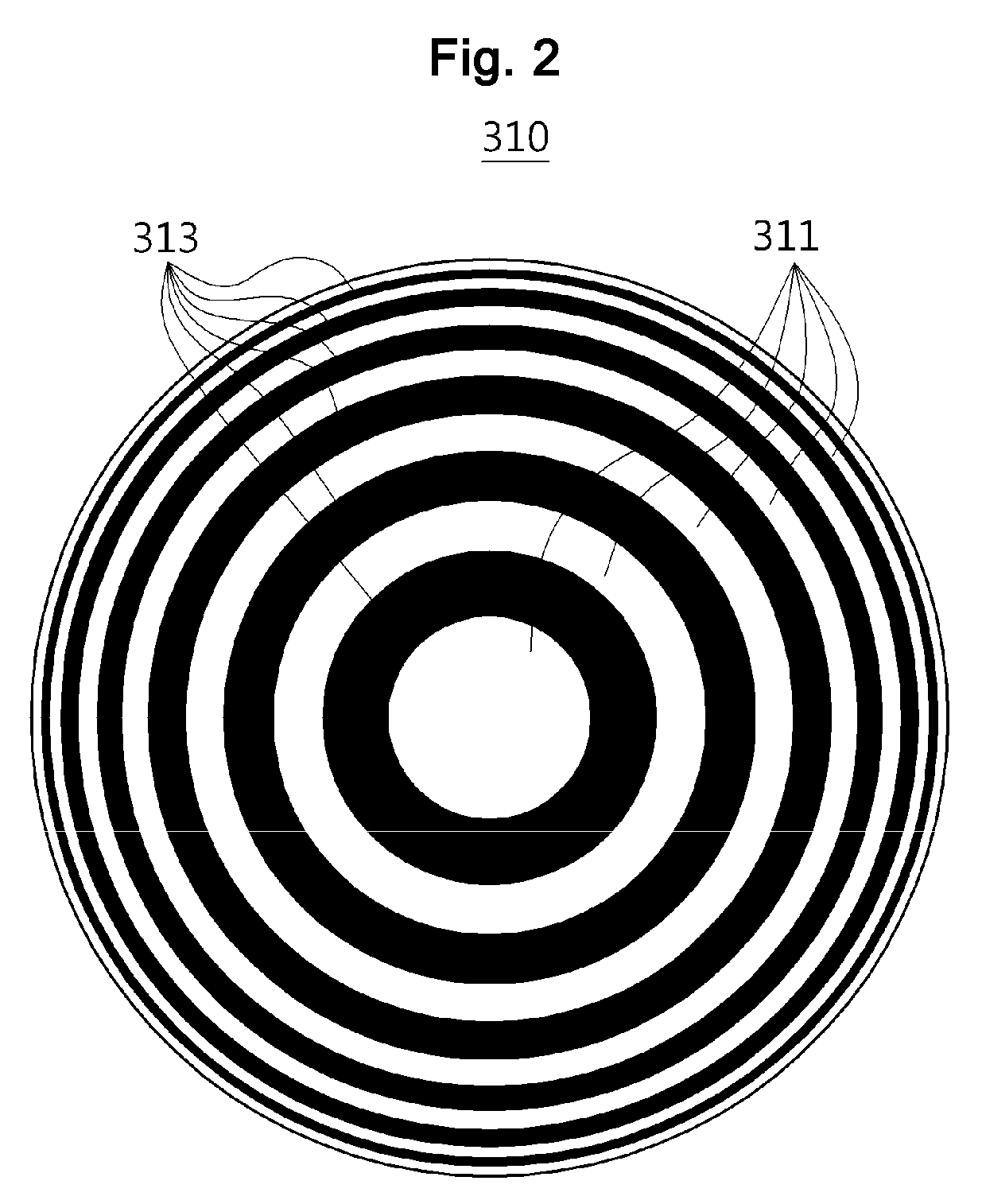
A Fresnel lens-integrated optical fiber that can be easily aligned and manufactured in miniature, and a method of fabricating the same are provided. The Fresnel lens-integrated optical fiber includes a light transmission section transmitting incident light, a light expansion section coupled to the light transmission section and expanding light provided from the light transmission section, and a Fresnel lens surface formed on a section of the light expansion section and focusing by passing through the light expanded in the light expansion section at a predetermined focal length. Accordingly, since the Fresnel lens surface has no curvature, arrangement of an optical coupling system is easy, manufacture is easy, and the optical coupling system can be miniaturized.

Description

CROSS-REFERENCE TO RELATED APPLICATION[0001]This application claims the benefit of Korean Patent Application No. 2008-0012389, filed on Feb. 11, 2008, the disclosure of which is hereby incorporated herein by reference in its entirety.BACKGROUND OF THE INVENTION[0002]1. Field of the Invention[0003]The present invention relates to an optical device, and more particularly, to a Fresnel lens-integrated optical fiber that can increase optical coupling efficiency in free space and can be easily manufactured, and a method of fabricating the same.[0004]2. Description of the Related Art[0005]Optical fiber lenses are used in the field of optical communications to increase optical coupling efficiency in free space when a light source and an optical fiber, an optical device and an optical fiber, or two optical fibers are coupled, and to manufacture a miniature optical coupling module. Recently, the optical fiber lenses are widely utilized in the field of biology such as optical imaging systems ...

Claims


Application Information

Patent Timeline
IPC IPC(8): G02B6/32B32B37/00B29D11/00
CPCG02B6/3582B29D11/00269B29D11/00663B29L2011/0075Y10T156/1052G02B6/2551G02B6/32G02B6/3512G02B6/3546G02B6/02295G02B6/028
Inventor LEE, BYEONG HAOH, KYUNGHWANKIM, JUN KICHOI, HAE YOUNGJUNG, YOUNGMINSOHN, IK-BUNOH, YOUNG-CHUILEE, JONGMIN
Owner GWANGJU INST OF SCI & TECH
Learn More