Optical scanning device and image forming apparatus
- Summary
- Abstract
- Description
- Claims
- Application Information
AI Technical Summary
Benefits of technology
Problems solved by technology
Method used
Image
Examples
first embodiment
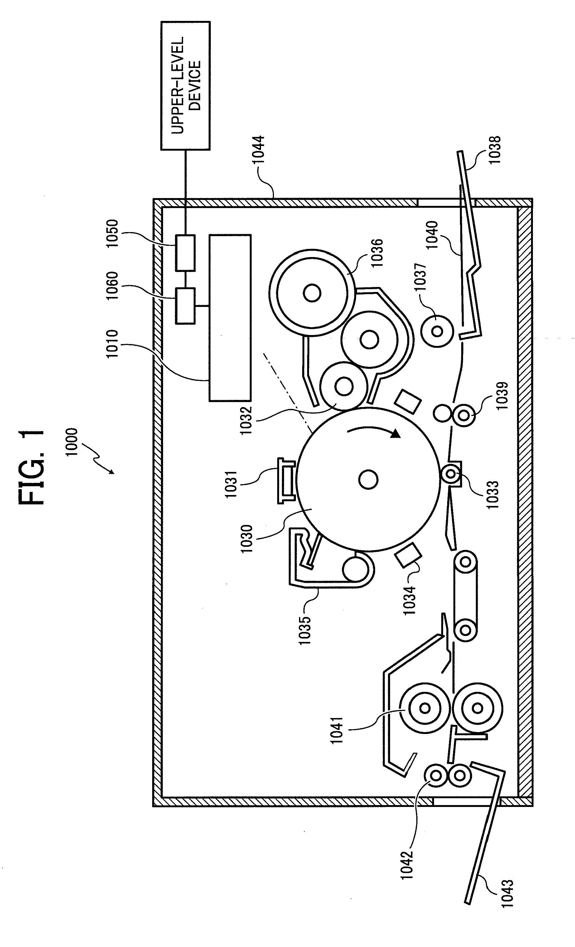
[0036]The laser printer 1000 includes an optical scanning device 1010 according to the present invention, a photosensitive drum 1030, a charging unit 1031, a developing roller 1032, a transfer charging unit 1033, a neutralizing unit 1034, a cleaning unit 1035, a toner cartridge 1036, a feed roller 1037, a feed tray 1038, a pair of registration rollers 1039, a fixing roller 1041, a discharge roller 1042, a discharge tray 1043, a communication control unit 1050, a printer control unit 1060 that controls each of the components, and so forth. These components are arranged at predetermined positions in a printer casing 1044.
[0037]The communication control unit 1050 controls a bi-directional communication with an upper-level device (e.g., a personal computer (PC)) via a network.
[0038]The photosensitive drum 1030 is a cylindrical member having a photosensitive layer formed on the surface thereof. The surface of the photosensitive drum 1030 is a scanning surface to be scanned. The photosens...
second embodiment
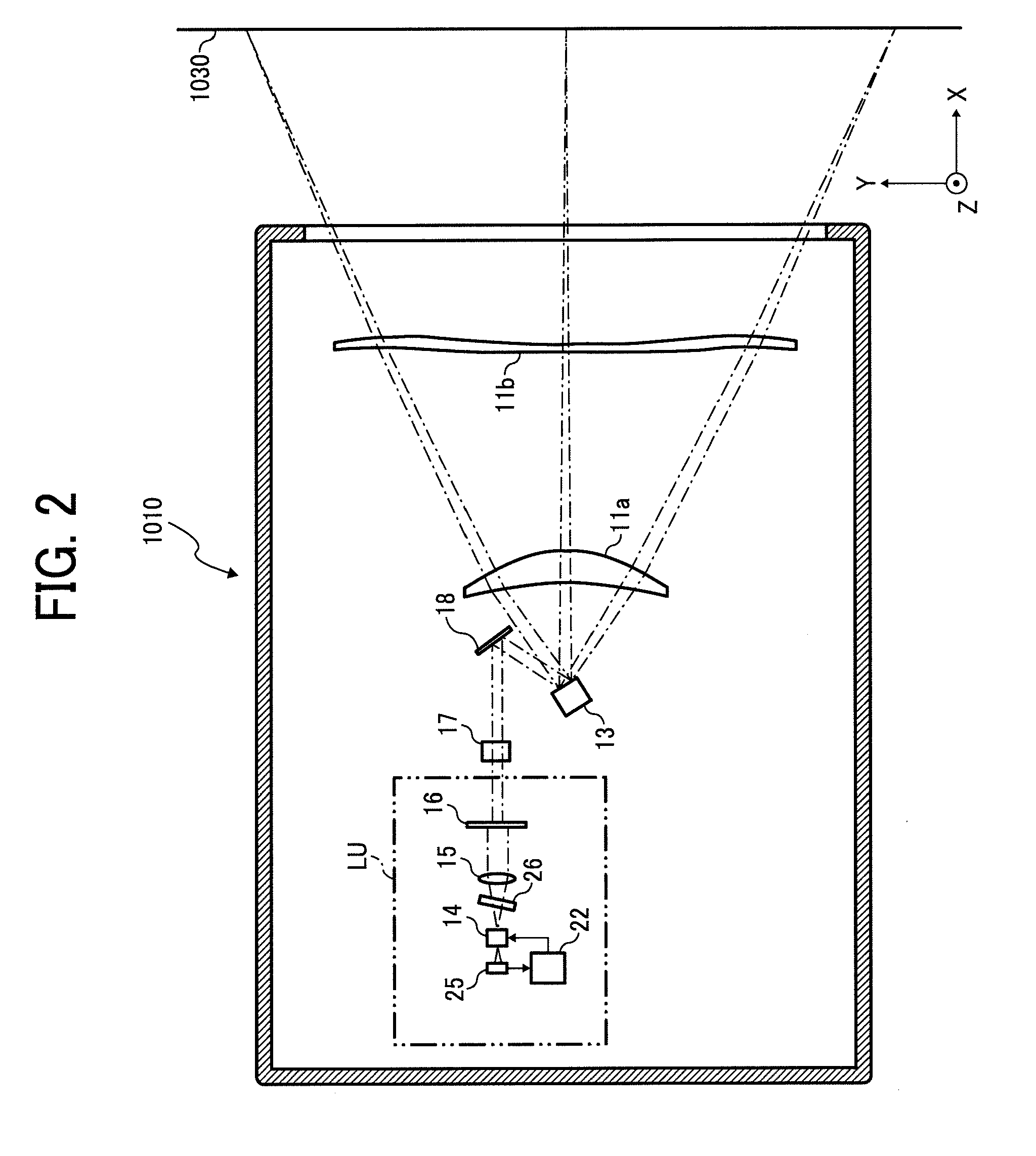
[0095]In the second embodiment, d=5.0 micrometers, Dm=30 micrometers, Ds=25 micrometers, Lm=Dm×9=270 micrometers, and Ls=d×39=194 micrometers, as shown in FIG. 12, where d is the spacing between adjacent light-emitting units when all the light-emitting units are orthogonally projected onto an imaginary line extending in the direction S, Dm is the spacing between adjacent light-emitting units in the direction M, Ds is the spacing between rows of the light-emitting units in the direction S, Lm is the spacing between the light-emitting units at both ends in the direction M, and Ls is the spacing between the light-emitting units at both ends in the direction S.
[0096]Each of the light-emitting units is a vertical-cavity surface-emitting laser (VCSEL) with an oscillation wavelength in a wavelength band of 780 nanometers. A light beam is emitted in the +X direction from each of the light-emitting units. In the design, the light beam emitted from each of the light-emitting units is assumed ...
third embodiment
[0111]A third embodiment according to the present invention will now be described with reference to FIGS. 14 to 16, 17A, 17B, 18A, 18B, 19, and 20. FIG. 14 is a schematic diagram of an exemplary structure of a color printer 2000, serving as an image forming apparatus according to the
[0112]The color printer 2000 is a tandem-type color printer that forms a full-color image by combining four colors (black, cyan, magenta, and yellow). The color printer 2000 includes an optical scanning device 2100, four photosensitive drums (2030a, 2030b, 2030c, and 2030d), four charging units (2032a, 2032b, 2032c, and 2032d), four developing rollers (2033a, 2033b, 2033c, and 2033d), four toner cartridges (2034a, 2034b, 2034c, and 2034d), four cleaning units (2031a, 2031b, 2031c, and 2031d), a transfer belt 2040, a feed tray 2060, a feed roller 2054, a pair of registration rollers 2056, a fixing roller 2050, a discharge tray 2070, a discharge roller 2058, a printer control unit (not shown in the figure)...
PUM
 Abstract
Description
Claims
Application Information
 - R&D
- Intellectual Property
- Life Sciences
- Materials
- Tech Scout
- Unparalleled Data Quality
- Higher Quality Content
- 60% Fewer Hallucinations
Browse by: Latest US Patents, China's latest patents, Technical Efficacy Thesaurus, Application Domain, Technology Topic, Popular Technical Reports.
© 2025 PatSnap. All rights reserved.Legal|Privacy policy|Modern Slavery Act Transparency Statement|Sitemap|About US| Contact US: help@patsnap.com


