
Contact metallization of carbon nanotubes

a carbon nanotube and contact technology, applied in the field of single-walled carbon nanotube metallization, can solve the problems of affecting the advancement of the topic, affecting the effect of the metallization process, and the inability to demonstrate the means of establishing individual electrical contacts and structural support of vertical swnts

Inactive Publication Date: 2009-08-06
PURDUE RES FOUND INC
View PDF17 Cites 18 Cited by
  • Summary
  • Abstract
  • Description
  • Claims
  • Application Information

AI Technical Summary

Benefits of technology

[0035]FIGS. 5.3(a)-5.3(d): Effect of multiple Fe layers. Cross-sectional FESEM images of a (a) single, (b) double, and (c) triple 0.5 nm Fe layer. (d) FESEM top view of porous template utilizing triple 0.5 nm Fe layer showing CNT emerging from pore. Scale bar=300 nm.
[0036]FIGS. 5.4(a)-5.4(d): Cross-sectional FESEM images showing effect of preanodization thermal diffusion on 2 nm Fe catalyst layer. Diffusi...

Problems solved by technology

Although new concepts for complex vertical carbon nanotube devices have been proposed in recent years, the means to establish individual electrical contacts and structural support to vertical SWNTs have not been demonstrated.
In part, the inability to synthesize vertical SWNTs in predefined locations has hindered advancement of the topic.
These procedures generally exhibit low yields and are limited to two-dimensional, planar architectures.
Although horizontal structures have proven invaluable for examination of SWNT transport properties and functional material selection, their flexibility is limited and precludes the exploitation of the nanometer-scale diameter of SWNTs as a scaling metric for device integration.
However, the inability to support and electrically address vertical nanotubes has prevented vertical devices from being realized.

Method used


Image

  • Contact metallization of carbon nanotubes
  • Contact metallization of carbon nanotubes
  • Contact metallization of carbon nanotubes

Examples


Embodiment Construction

[0046]For the purposes of promoting an understanding of the principles of the invention, reference will now be made to the embodiments illustrated in the drawings and specific language will be used to describe the same. It will nevertheless be understood that no limitation of the scope of the invention is thereby intended, such alterations and further modifications in the illustrated device, and such further applications of the principles of the invention as illustrated therein being contemplated as would normally occur to one skilled in the art to which the invention relates.

[0047]This application incorporates by reference U.S. provisional patent application Ser. No. 60 / 747,422, filed 17 May 2006.

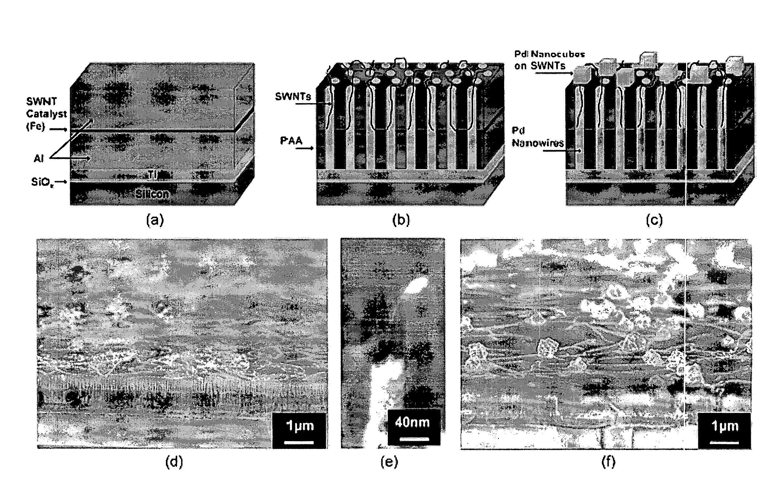
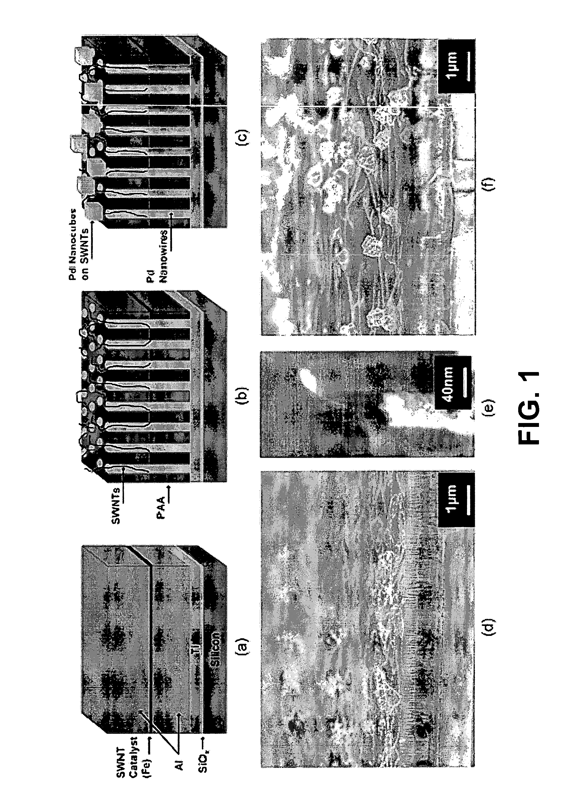
[0048]Some embodiments of the present invention provide a procedure for electrically contacting vertical carbon nanotubes with nanoscale metallic wires and / or particles. Current means for establishing electrical contacts with nanotubes involves photolithography or electron-beam lithography...


PUM

PropertyMeasurementUnit
Sizeaaaaaaaaaa
Sizeaaaaaaaaaa
Electrical conductivityaaaaaaaaaa

Abstract

In one embodiment, SWNTs are synthesized from an embedded catalyst in a modified porous anodic alumina (PAA) template. Pd is electrodeposited into the template to form nanowires that grow from an underlying conductive layer beneath the PAA and extend to the initiation sites of the SWNTs within each pore. Individual vertical channels of SWNTs are created, each with a vertical Pd nanowire back contact. Further Pd deposition results in annular Pd nanoparticles that form on portions of SWNTs extending onto the PAA surface. Two-terminal electrical characteristics produce linear I-V relationships, indicating ohmic contact in the devices.

Description

CROSS REFERENCE TO RELATED APPLICATIONS[0001]This application is a CIP of U.S. patent application Ser. No. 12 / 024,635, filed Feb. 1, 2008, all of which is incorporated herein by reference.FIELD OF THE INVENTION[0002]These inventions pertain to methods and apparatus for metallizing nanotubes, and in particular to metallization of single-walled carbon nanotubes (SWNTs).BACKGROUND OF THE INVENTION[0003]Although new concepts for complex vertical carbon nanotube devices have been proposed in recent years, the means to establish individual electrical contacts and structural support to vertical SWNTs have not been demonstrated. In part, the inability to synthesize vertical SWNTs in predefined locations has hindered advancement of the topic. Various embodiments of the invention include both a robust process to synthesize SWNTs reproducibly in vertical, long-range ordered channels suitable for device integration and a facile means to contact the top and bottom of SWNTs simultaneously without...

Claims


Application Information

Patent Timeline
IPC IPC(8): H01B1/04C25D5/02C25D5/44
CPCB01J21/185C25D11/045B01J35/023B01J35/10B01J37/0238B01J37/0244B01J37/347B01J37/348B82Y10/00B82Y30/00B82Y40/00C01B31/0233C01B31/0253C01B2202/02C01B2202/08C01P2004/13C25D1/02C25D1/10C25D3/50C25D5/02C25D5/18C25D7/00B01J23/745C01B32/162C01B32/168B01J35/60B01J35/40
Inventor FRANKLIN, AARON D.MASCHMANN, MATTHEW R.FISHER, TIMOTHY S.SANDS, TIMOTHY D.
Owner PURDUE RES FOUND INC
Learn More