
Elastic laminate and method of making

a technology of elastic laminate and elastic side panels, which is applied in the field of tear-resistant elastic laminate, can solve the problems of not having sufficient tear resistance for use in high-strength side panels, webs that typically do not have sufficient tear resistance, and short of teaching a method to make tear-resistant elastic side panels

Active Publication Date: 2009-07-30
ADVANTAGE CREATION ENTERPRISE
View PDF46 Cites 65 Cited by
  • Summary
  • Abstract
  • Description
  • Claims
  • Application Information

AI Technical Summary

Benefits of technology

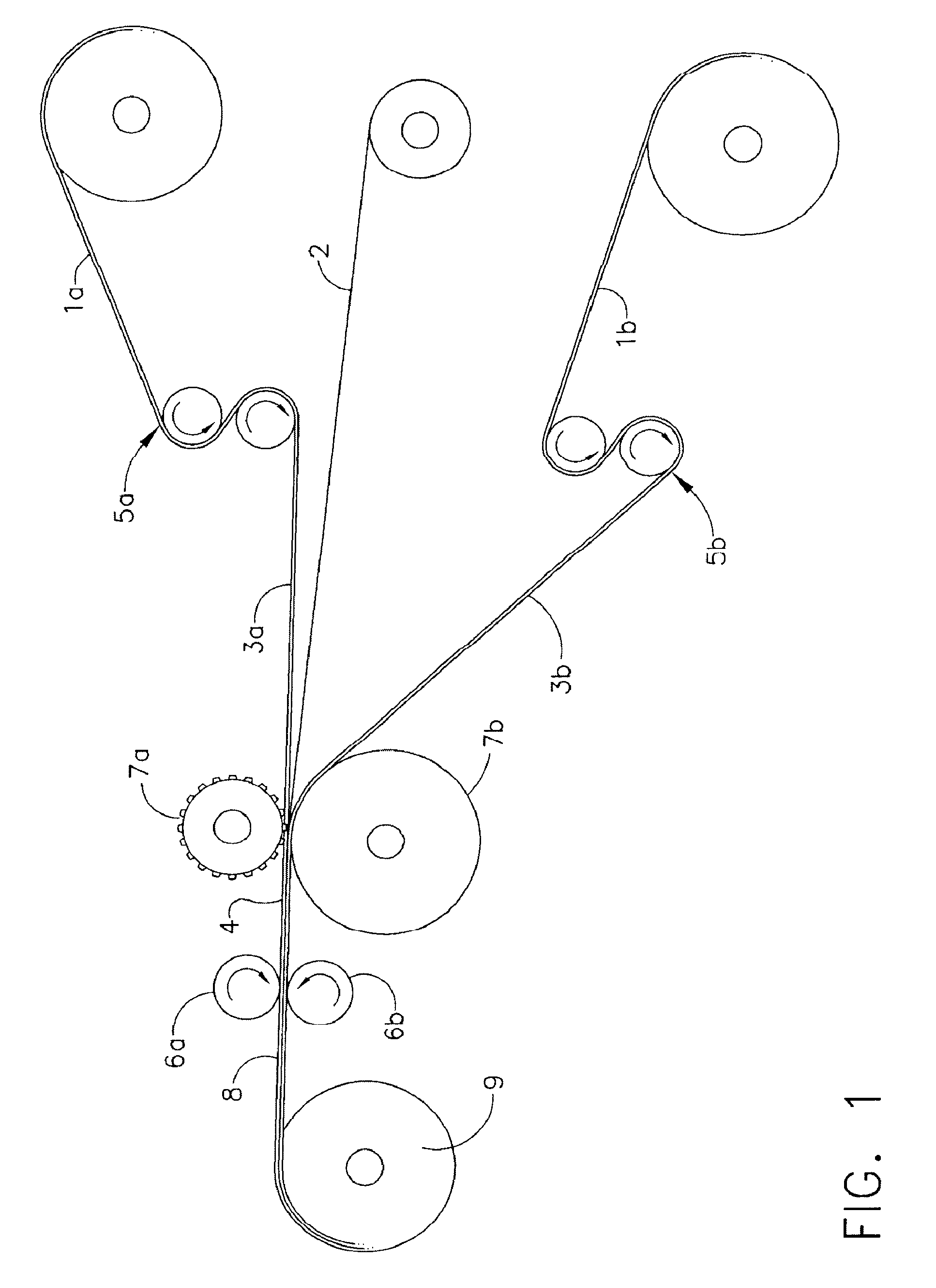
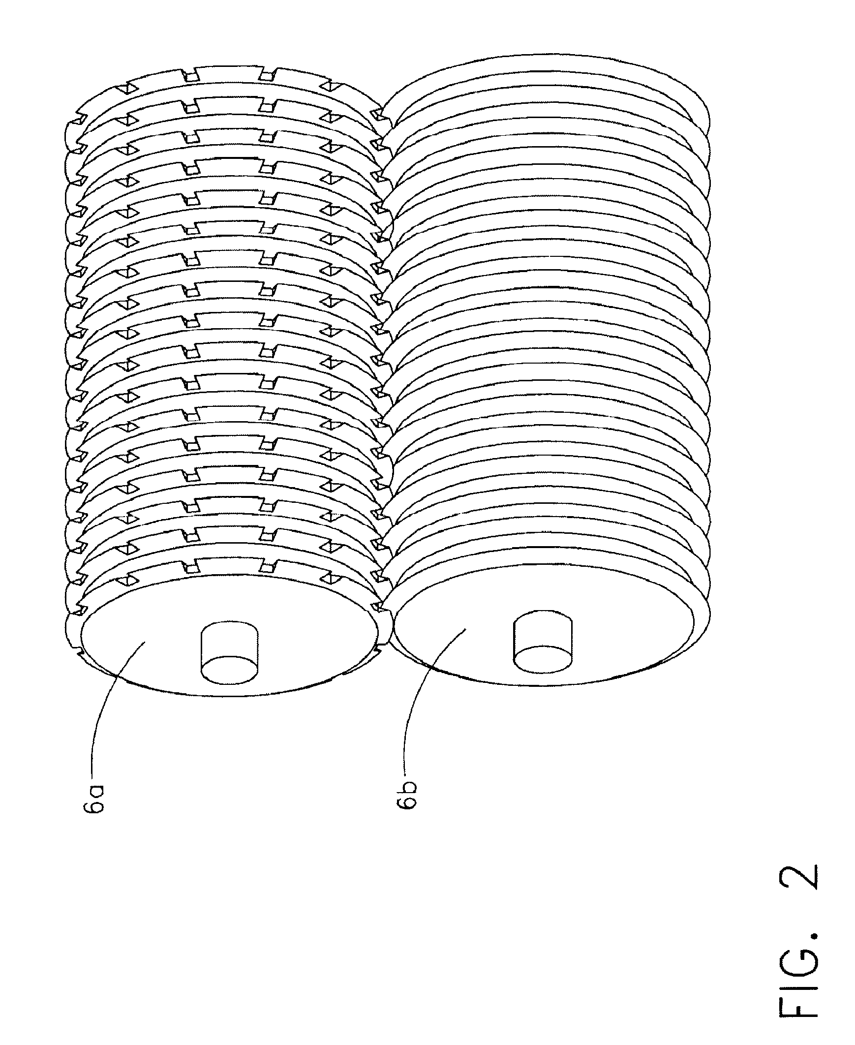
[0009]The present invention relates to an elastic laminate comprising an elastic substrate bonded to at least one layer of a tensioned spunbond nonwoven web comprising thermoplastic filaments comprising at least about 10% by weight polyethylene, said laminate being incrementally stretched in the transverse direction to provide a service stretch greater than 100% and a strength ratio greater than 0.35.

Problems solved by technology

However such webs typically do not have sufficient tear resistant strength to make them suitable for use as diaper side panels.
However, such a laminate may not have sufficient tear resistance for use in high stretch side panel applications.
While the above patents and applications disclose various methods for forming elastic laminates, many fall short of teaching a method to make an elastic laminate for diaper side panels that is tear resistant when subjected to high strain or stress.
Since tear resistance is achieved by using highly bulked nonwovens, this process is not suitable for diaper side panels since it will inhibit anchoring the closure tape to the elastic film and require the use of a deadened zone to act as a linkage between the elastic laminate and the closure tape.

Method used


Image

  • Elastic laminate and method of making
  • Elastic laminate and method of making
  • Elastic laminate and method of making

Examples


Embodiment Construction

[0025]As used herein, the term “machine direction” means the direction in which precursor webs are formed, which is the longitudinal direction of an uncut web.

[0026]As used herein, the term “transverse direction” means the cross direction, disposed at 90° to the machine direction, and extends across the width of the precursor web.

[0027]As used herein, the term “relaxed state” means the only tension applied to the material is a low winding tension exhibited by the winder to prevent the web from getting stuck in the bonding nip.

[0028]As used herein, the term “tensioned state” means that the web is under machine direction strain or a combination of radiant heat and machine direction strain that forces it to shrink at least 10%, but less than 40%, in the transverse direction from its unsupported edges.

[0029]As used herein, the term “strength ratio” refers to the ultimate tensile tear strength in newtons per 2 linear inches of the laminate divided by the basis weight in g / m2 of the lamin...


PUM

PropertyMeasurementUnit
shrinkageaaaaaaaaaa
shrinkageaaaaaaaaaa
shrinkageaaaaaaaaaa

Abstract

An elastic laminate for use as a tear resistant diaper side panel. The elastic laminate comprises an elastic substrate bonded to at least one layer of a tensioned spunbond nonwoven web comprising thermoplastic filaments comprising at least about 10% by weight polyethylene. The laminate is then incrementally stretched in the transverse direction to provide a service stretch greater than 100% and a strength ratio greater than 0.35. In one embodiment, the elastic substrate is bonded between the tensioned nonwoven webs by point bonding or hot melt adhesives. Also disclosed is a method for making an elastic laminate comprising the steps of providing at least one layer of a tensioned spunbond nonwoven web comprising thermoplastic filaments comprising at least about 10% by weight polyethylene, providing an elastic substrate, bonding the elastic substrate and the at least one layer of nonwoven web to provide an elastic laminate, and incrementally stretching the laminate in the transverse direction to provide a service stretch greater than 100% and a strength ratio greater than 0.35.

Description

CROSS-REFERENCE TO RELATED APPLICATION[0001]This application claims the benefit of co-pending U.S. Provisional Application No. 61 / 024,742, filed Jan. 30, 2008.TECHNICAL FIELD[0002]This invention relates to a tear resistant elastic laminate suitable for use as a diaper side panel. The laminate comprises an elastic substrate bonded to at least one layer, and typically between two layers, of a tensioned spunbond nonwoven web comprising thermoplastic filaments comprising polyethylene. The laminate is then incrementally stretched in the transverse direction to provide a service stretch greater than 100% and a strength ratio greater than 0.35. The invention also relates to a method for making such an elastic laminate. In one embodiment, the laminate is used as a diaper elasticated ear.BACKGROUND OF THE INVENTION[0003]Nonwoven covered elastic fabrics are used in various industrial and consumer products sectors. In particular, webs of nonwoven elastic fabric are used to produce disposable s...

Claims


Application Information

Patent Timeline
Patent Type & Authority Applications(United States)
IPC IPC(8): D04H3/02B32B37/14
CPCA61F13/15593B29C66/438A61F13/56B29C55/023B29C55/18B29C65/02B29C65/08B29C65/18B29C66/0324B29C66/21B29C66/344B29C66/83411B29C66/83413B29C66/83511B29C2793/009B29K2009/06B29K2021/00B29K2023/06B29K2023/0633B29K2023/083B29K2023/12B29K2075/00B29K2101/12B29K2105/0085B29K2105/0854B29K2105/24B29K2223/00B29K2223/06B29K2301/12B29K2313/00B29K2995/0046B29L2031/4878B32B37/0053B32B37/0076B32B37/144B32B2037/1215B32B2038/0028B32B2305/20B32B2307/51B32B2307/54B32B2307/718B32B2309/14B32B2310/0868B32B2323/04B32B2555/02D04H13/006D04H13/007A61F13/4902B29C65/4815B29C66/7294B29C65/00B29C66/1122B29C66/433B29C66/71B29C66/712B29C66/73711B29C66/73755B29C66/73773B29C66/7379B29C66/73791B29C66/7392B29C66/73921B29C66/7394D04H1/56D04H1/593D04H3/14Y10T442/601Y10T442/637Y10T442/66Y10T442/674B29K2023/04B29K2033/08B29K2025/08B29K2023/16B29K2023/10B29K2023/08B29K2023/00
Inventor CREE, JAMES W.
Owner ADVANTAGE CREATION ENTERPRISE
Learn More