
Angled flying lead wire bonding process

a technology of flying lead wire and bonding process, which is applied in the direction of manufacturing tools, instruments, non-electric welding apparatus, etc., can solve the problem that the conventional wire bonding process is not useful in fabricating such structures

Inactive Publication Date: 2009-07-30
GLOBALFOUNDRIES INC
View PDF5 Cites 113 Cited by
  • Summary
  • Abstract
  • Description
  • Claims
  • Application Information

AI Technical Summary

Benefits of technology

The present invention provides a process for bonding wires to an electronic circuit device with one end attached to the surface of the device and the other end extending away from the surface. The wires can also be formed at an angle or have curved features. This process allows for more efficient and secure bonding of wires to the device.

Problems solved by technology

If it is desired that the wires bonded to the surface be used as an electronic device probe (as described herein) or to interconnect an array of contact pads on a first surface to another array of contact pads on a second surface which is facing the first surface, the conventional wire bonding process is not useful to fabricate such structures.

Method used


Image

  • Angled flying lead wire bonding process
  • Angled flying lead wire bonding process
  • Angled flying lead wire bonding process

Examples


Embodiment Construction

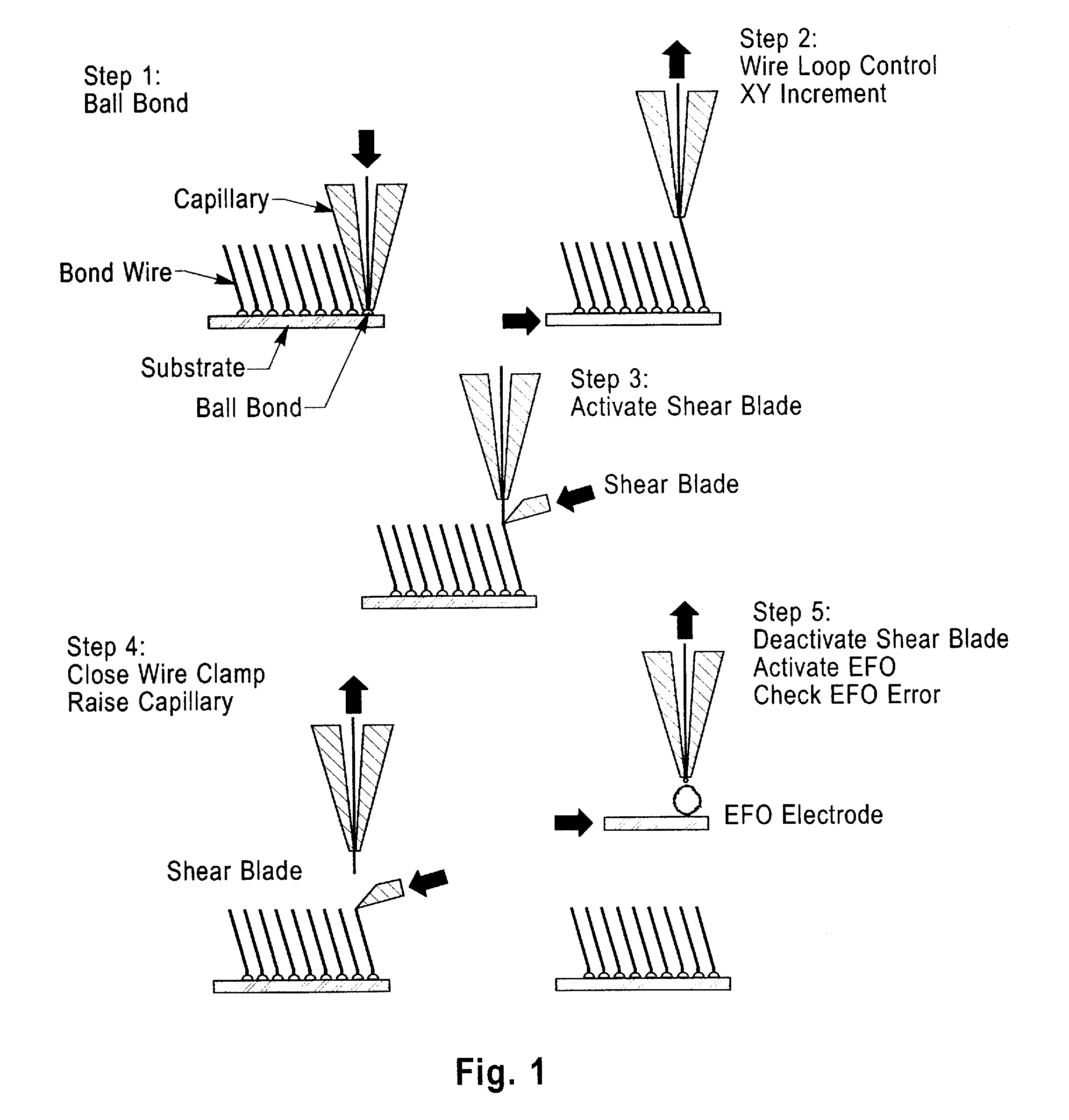
[0019]Structures according to the present invention are made using a wire bonding operation is shown in FIG. 1 and starts by forming a ball on the end of a (preferably) gold wire 110 that is threaded through a hollow pointed ceramic tool called a capillary 115. The ball 112 is pressed against the first bonding surface 116 of substrate 118 while the substrate 118 is heated from below and ultrasonic energy is applied through the capillary 115 as shown in step 1 of FIG. 1. The metallurgy on the surface of the substrate is critical to the wire bonding process. After ball bonding the wire to the first substrate surface 116, the capillary 115 is raised while the substrate is moved (shown by arrow 120) to create a loop shape in the wire (FIG. 1—step 2). The capillary 115 is then lowered to press the side 124 of the wire against the second substrate 126 surface 128 to form the second bond or wedge bond 130 (FIG. 1—step 3). The capillary is raised slightly indicated by arrow 132 and a mechan...


PUM

PropertyMeasurementUnit
diameteraaaaaaaaaa
diameteraaaaaaaaaa
plurality of anglesaaaaaaaaaa

Abstract

A method is described having the steps of providing a surface having a plurality of wire bondable locations; wire bonding a wire to each of the wire bondable locations using a wire capillary tool; controlling the position of the capillary tool with respect to the substrate; after forming a wire bond of the wire to the wire bondable location moving the capillary tool relative to the surface as the capillary tool is moved away from the surface to form a wire having a predetermined shape.

Description

[0001]This application is a Continuation of, application Ser. No. 10 / 736,890, filed on Dec. 16, 2003, U.S. Pat. No. 7,495,342, which is a Division of application Ser. No. 10 / 342,167, filed on Jan. 14, 2003, U.S. Pat. No. 6,708,403, which is a Continuation of application Ser. No. 09 / 871,536, filed on May 31, 2001, U.S. Pat. No. 6,526,655, which is a Division of application Ser. No. 09 / 164,470, filed on Oct. 1, 1998, U.S. Pat. No. 6,295,729, which is a Continuation-in-part of application Ser. No. 09 / 088,394, filed on Jun. 1, 1998, U.S. Pat. No. 6,300,780 which Claims Priority from Provisional Application No. 60 / 060,877, filed on Oct. 2, 1997, which is a Division of application Ser. No. 08 / 754,869, filed on Nov. 22, 1996, U.S. Pat. No. 5,821,763, which is a continuation of application Ser. No. 08 / 055,485, filed Apr. 30, 1993, U.S. Pat. No. 5,635,846, which is a Continuation-in-part of application Ser. No. 07 / 963,346, filed on Oct. 19, 1992, U.S. Pat. No. 5,371,654.FIELD OF THE INVENTIO...

Claims


Application Information

Patent Timeline
Patent Type & Authority Applications(United States)
IPC IPC(8): H01L23/49H01R43/02B23K20/00G01R1/067G01R1/073G01R3/00H01L21/00H01L21/48H01L21/60H01L21/607H01L23/32
CPCB23K20/004Y10T29/49179B23K2201/40G01R1/06711G01R1/0675G01R1/07307G01R1/07371G01R3/00H01L21/4853H01L21/4896H01L24/11H01L24/13H01L24/14H01L24/45H01L24/78H01L24/85H01L2224/0401H01L2224/0603H01L2224/1134H01L2224/13016H01L2224/1403H01L2224/16H01L2224/45144H01L2224/78301H01L2224/85205H01L2924/01006H01L2924/01014H01L2924/01027H01L2924/01028H01L2924/01029H01L2924/01032H01L2924/01042H01L2924/01046H01L2924/01075H01L2924/01077H01L2924/01078H01L2924/01079H01L2924/01082H01L2924/14B23K20/007Y10T29/49174Y10T29/49144Y10T29/49194Y10T29/49149Y10T29/4921H01L2924/01045H01L2924/01044H01L2924/01033H01L2924/00013H01L2924/00014H01L2224/13099H01L2224/48H01L2924/00B23K2101/40H01L2224/45015H01L2224/7855H01L2924/20755H01L2924/20756H01L2924/20757H01L2924/2075H01L2924/20754H01L2924/00012
Inventor BEAMAN, BRIAN SAMUELFOGEL, KEITH EDWARDLAURO, PAUL ALFREDSHIH, DA-YUAN
Owner GLOBALFOUNDRIES INC
Learn More