
Submersible plant

a technology of submerged plants and propellers, applied in the direction of propellers, propulsive elements, water-acting propulsive elements, etc., can solve the problem of inherently intermittent wind energy

Active Publication Date: 2009-07-23
MINESTO
View PDF10 Cites 39 Cited by
  • Summary
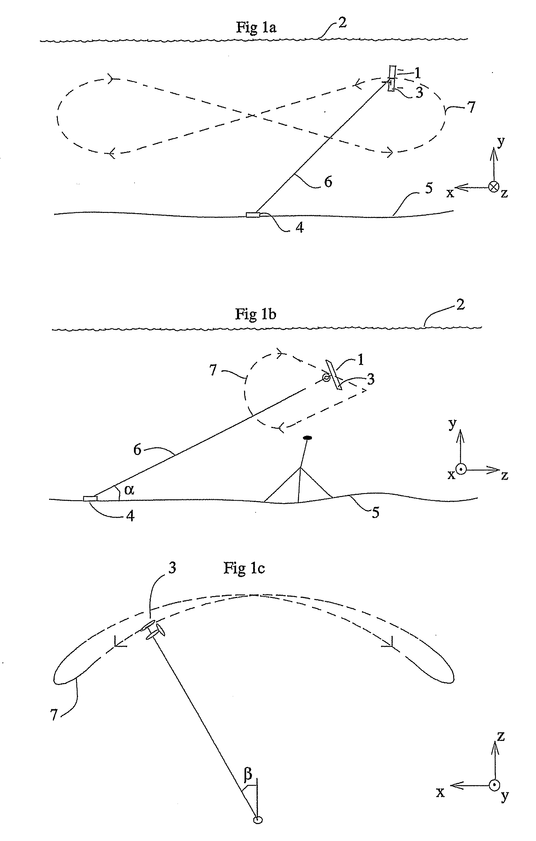
  • Abstract
  • Description
  • Claims
  • Application Information

AI Technical Summary

Benefits of technology

[0009]The plant is preferably mounted in environments with well-defined, predictable streams with regard to direction and velocity such as in rivers, in tide affected areas and in ocean streams.
[0010]The plant in accordance of the invention enables environment friendly, rational and cost effective generation of energy, for example electrical energy, from relatively weak ocean currents and tide streams on cites close to the coast. The plant in accordance with the present invention can also be used offshore at relatively large depths, where few competing techniques are available.
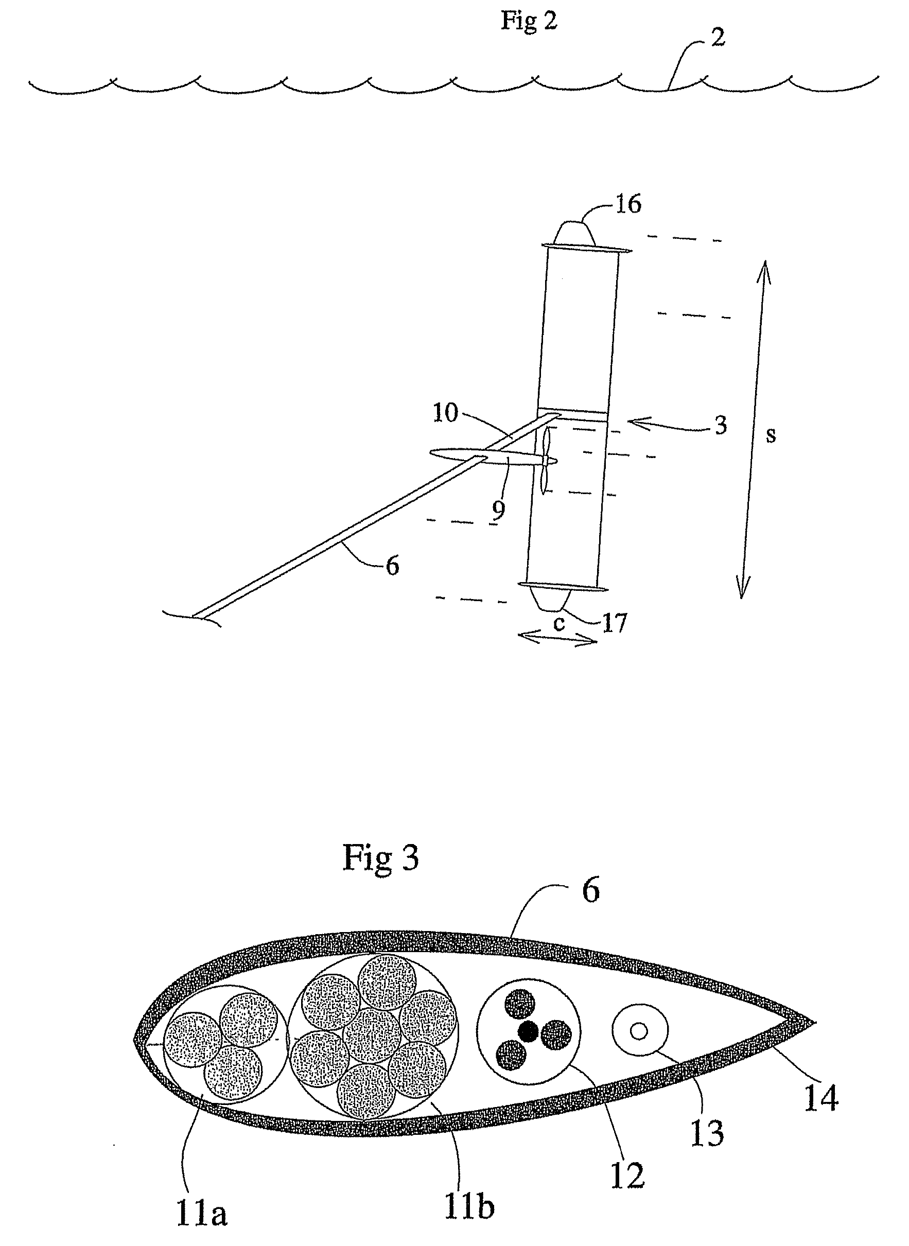
[0012]The vehicle is in accordance with another preferred embodiment substantially free swiveling at least in a pitch direction. The vehicle adapts to an optimum working point in the pitch direction. The vehicle is preferably also free swiveling in a roll direction in relation to the turbine. Thereby the turbine will face the relative stream direction, ie the water stream will be forced upon the turbine from a direction perpendicular to a plane defined by the turbine blades.

Problems solved by technology

One of the main global problems to be solved is how to supply energy to the population of the world.
The wind powered generating systems have a problem in that wind energy is inherently intermittent.

Method used


Image

  • Submersible plant
  • Submersible plant
  • Submersible plant

Examples


Embodiment Construction

[0006]One object to the invention is to increase the power output from submersible plants.

[0007]This has been achieved by means of a submersible plant for producing energy comprising at least one turbine and characterized in that said turbine is mounted on a stream-driven vehicle and in that said stream-driven vehicle is secured in a structure by means of at least one wire. The structure can be stationary, such as a mooring at the bottom of a sea, river, lake etc or a wind power plant or stationary submersible plant located in a sea or lake. The structure can also be movable, such as a ship.

[0008]The vehicle of the plant according to the present invention moves with a velocity which is many times (characteristically between 10-20 times) higher than the streaming velocity of the water. Thereby, the efficiency of the on board turbine arrangement is much higher than the efficiency of a stationary rotor arrangement.

[0009]The plant is preferably mounted in environments with well-defined,...


PUM


Abstract

The present invention relates to a submersible plant for producing energy. The submersible plant comprises at least one turbine (9) and is characterized in that said turbine (9) is mounted on a stream-driven vehicle (3) and in that said stream-driven vehicle is secured in a structure by means of at least one wire (6).

Description

TECHNICAL AREA[0001]The present invention relates to a submersible plant for producing energy comprising at least one turbine.DESCRIPTION OF PRIOR ART[0002]One of the main global problems to be solved is how to supply energy to the population of the world. The use of fossil fuels has to be decreased and substituted with renewable sources of energy.[0003]A significant percentage of the efforts to use renewable sources of energy have been concentrated on wind powered systems. The wind powered generating systems have a problem in that wind energy is inherently intermittent.[0004]There exist today submersible plants for producing electricity from ocean currents. Those plants are fastened in the sea bottom by means of wires and comprise turbines arranged to be driven by tidal water.[0005]However, the power generated from the submersible plants needs to be increased without substantially increasing the costs in order to be commercially attractive.DESCRIPTION OF THE INVENTION[0006]One obje...

Claims


Application Information

Patent Timeline
IPC IPC(8): F03B17/06F03B13/10
CPCF03B17/00F03D5/00F05B2240/917F03B17/061F05B2240/97Y02E10/28Y02E10/728Y02E10/70F03B17/06Y02E10/30F05B2240/9174Y02E10/20
Inventor LANDBERG, MAGNUS
Owner MINESTO
Learn More