
QKD system and method with improved signal-to-noise ratio

a signal-to-noise ratio and signal-to-noise ratio technology, applied in the field ofquantum cryptography, can solve the problems of two wave packets together, slight mismatches in the differential optical path length, and introduction errors that reveal her presence, and achieve the effects of improving the signal-to-noise ratio (snr), small qubit error rate, and high qubit ra

Inactive Publication Date: 2009-07-23
MAGIQ TECH INC
View PDF6 Cites 20 Cited by
  • Summary
  • Abstract
  • Description
  • Claims
  • Application Information

AI Technical Summary

Benefits of technology

[0010]The present invention is directed to systems and methods for performing quantum key distribution (QKD) that allow for an improved signal-to-noise ratio (SNR) when providing active compensation of the system's relative optical paths. The method includes generating a train of quantum signals having a first wavelength and interspersing at least one and preferably a relatively large number of strong control signals having a second wavelength in between the quantum signals. Only the quantum signals are modulated when the quantum and control signals travel over the first optical path at Alice. The quantum and control signals are sent to Bob, where only the quantum signals are modulated as both signal types travel over a second optical path at Bob. The control signals are directed to two different photodetectors by an optical splitter. The proportion of optical power detected by each photodetector represents the optical path difference (i.e., phase error) between the first and second optical paths. This difference is then compensated via a control signal sent to a path-length-adjusting (PLA) element in one of the optical paths. The strong control signals provides a high SNR that allows for commercially viable QKD system that can operate with a high qubit rate and a small qubit error rate (QBER) in the face of real-world sources of noise. Example embodiments using a fiber-based, phase-modulated QKD system and a PLA element in the form of an actuator residing in a section of optical fiber and that can change the phase of light passing therethrough, are discussed in detail below.

Problems solved by technology

As a consequence, an eavesdropper (“Eve”) that attempts to intercept or otherwise measure the exchanged qubits will introduce errors that reveal her presence.
The first unbalanced interferometer, located with Alice, splits a single photon into two spatially separated wave packets and the second unbalanced interferometer, located in Bob, brings the two wave packets together and interferes them.
Because the two unbalanced interferometers are located remotely from each other, slight mismatches in the differential optical path lengths can arise from local environmental effects, including thermal fluctuations, acoustic noise, and vibrations.
A mismatch in the differential optical path lengths result in a phase error that reduces the degree of interference of the single-photon-level optical pulses (“quantum pulses”).
This in turn increases the quantum bit-error rate (QBER), which reduces the efficiency of the QKD process.
Since SPDs are still sensitive photo-detectors during the time intervals between gating pulses, any classical signals reaching them generate an enormous number of electrons, some of which become trapped in the APD junction and cause spontaneous avalanches as soon as gating pulses are applied.
This increases the signal-to-noise ratio (SNR) at the expense of tracking bandwidth.
If the vibration amplitude is stronger, the system may not be able to track it, which leads to an increase in the QBER.
While this may provide satisfactory operation for laboratory and experimental conditions, it does not provide sufficient bandwidth for a commercially viable QKD system that requires tracking high-frequency, high-amplitude vibrations, such as for example, those coupled into the interferometers by system fan noise.
The main disadvantages of this approach, however, are the higher excess loss of these interferometers compared to fiber based interferometers and the fact these components are not readily available and are difficult to manufacture.

Method used


Image

  • QKD system and method with improved signal-to-noise ratio
  • QKD system and method with improved signal-to-noise ratio
  • QKD system and method with improved signal-to-noise ratio

Examples


Embodiment Construction

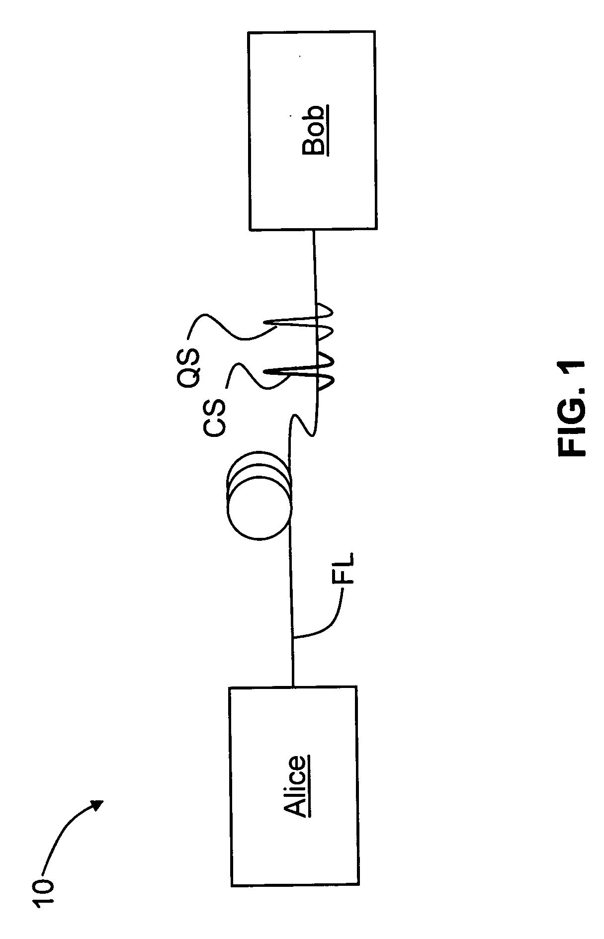
[0018]FIG. 1 is a schematic diagram of an actively stabilized QKD system 10 according to the present invention. QKD system 10 includes a QKD station Alice and a QKD station Bob that are optically coupled. In the example embodiment of FIG. 1, Alice and Bob are optically coupled by an optical fiber link FL. Alice and Bob communicate by encoded single-photon-level quantum signals QS having a wavelength λQ. The encoding may be any type of encoding that changes the state of the photon. Usually, polarization encoding or phase encoding is used, as described in Bouwmeester. The present invention applies to any type of encoding scheme and QKD system that requires active stabilization in order to maintain the qubit error rate (QBER) at an acceptable level. For example, in a polarization-based QKD system, a polarized control signal is sent over the optical fiber link FL and is used to determine changes in the polarization state over the QKD system optical path.

[0019]In the present invention, t...


PUM


Abstract

Systems and methods for performing quantum key distribution (QKD) that allow for an improved signal-to-noise ratio (SNR) when providing active compensation for differences that arise in the system's relative optical paths. The method includes generating at one QKD station (Alice) a train of quantum signals having a first wavelength and interspersing one or more strong control signals having a second wavelength in between the quantum signals. Only the quantum signals are modulated when the quantum and control signals travel over the first optical path at Alice. The quantum and control signals are sent to Bob, where only the quantum signals are modulated as both signal types travel over a second optical path at Bob. The control signals are directed to two different photodetectors by an optical splitter. The proportion of optical power detected by each photodetector represents the optical path difference between the first and second optical paths. This difference is then compensated for via a control signal sent to a path-length-adjusting element in one of the optical paths. The control signals provides a high SNR that allows for commercially viable QKD system that can operate with a high qubit rate and a small qubit error rate (QBER) in the face of real-world sources of noise.

Description

FIELD OF THE INVENTION[0001]The present invention relates generally to quantum cryptography, and in particular to actively stabilized quantum key distribution (QKD) systems.BACKGROUND ART[0002]QKD involves establishing a key between a sender (“Alice”) and a receiver (“Bob”) by using either single-photons or weak (e.g., 0.1 photon on average) optical signals (pulses) called “qubits” or “quantum signals” transmitted over a “quantum channel.” Unlike classical cryptography whose security depends on computational impracticality, the security of quantum cryptography is based on the quantum mechanical principle that any measurement of a quantum system in an unknown state will modify its state. As a consequence, an eavesdropper (“Eve”) that attempts to intercept or otherwise measure the exchanged qubits will introduce errors that reveal her presence.[0003]The general principles of quantum cryptography were first set forth by Bennett and Brassard in their article “Quantum Cryptography: Publi...

Claims


Application Information

Patent Timeline
Patent Type & Authority Applications(United States)
IPC IPC(8): H04L9/08
CPCH04L9/0858
Inventor BEAL, A. CRAIG
Owner MAGIQ TECH INC
Learn More