Microstructure roller, microstructure fabrication method, tool for fabricating a microstructure roller

a microstructure and roller technology, applied in the field of roller technology, can solve the problems of high equipment cost of these conventional manufacturing methods, high cost of etching equipment, complicated and labor-intensive conventional processes,

Inactive Publication Date: 2009-07-23
NAT TAIWAN UNIV
View PDF21 Cites 7 Cited by
  • Summary
  • Abstract
  • Description
  • Claims
  • Application Information

AI Technical Summary

Benefits of technology

[0005]It is, therefore, the primary object of the present invention to provide a microstructure roller fabrication method, which u

Problems solved by technology

However, the equipment cost of these conventional manufacturing methods is high.
Further, these conventional processes are complicated and requiring much labor and time.
However, an etching equipment is quite expensive.
Further, it is very difficult to etch notches on

Method used


Image

  • Microstructure roller, microstructure fabrication method, tool for fabricating a microstructure roller
  • Microstructure roller, microstructure fabrication method, tool for fabricating a microstructure roller
  • Microstructure roller, microstructure fabrication method, tool for fabricating a microstructure roller

Examples


Embodiment Construction

[0019]Please refer to FIGS. 2˜4, a microstructure roller fabrication method for fabricating a microstructure roller in accordance with one example of the present invention is shown comprising, at first, the step of preparing a flexible mold plate 22 and a cylinder 24 (see FIG. 2). The flexible mold plate 22 has an array of micro lens male dies 221 arranged on its one side, forming a patterned face 220. The cylinder 24 has an axial hole 245, and a groove 243 extending around the periphery 241.

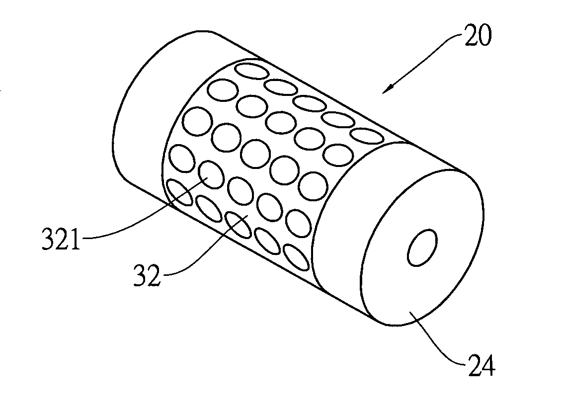
[0020]The patterned face 220 of the flexible mold plate 22 is then adhered to the periphery 241 of the cylinder 24 so that a cavity is defined in between the flexible mold plate 22 and the groove 243. Thereafter, a prepared resin 30 is filled in the cavity in between the flexible mold plate 22 and the groove 243, and then cured (see FIG. 3). After the resin 30 is cured, remove the flexible mold plate 22 from the cylinder 24, and the desired microstructure roller 20 is thus obtained (see FIG. 4)....


PUM

PropertyMeasurementUnit
Flexibilityaaaaaaaaaa
Microstructureaaaaaaaaaa

Abstract

A microstructure roller formed of a cylinder and a resin pattern layer is disclosed. The microstructure roller is made by: providing a cylinder having a groove extending around the periphery, and then adhering a flexible mold plate to the periphery of the cylinder to have a cavity be defined in between the groove of the cylinder and a patterned face of microstructure patterns of the flexible mold plate, and then filling a resin in the cavity, and the curing the resin, and then removing the flexible mold plate from the cylinder.

Description

BACKGROUND OF THE INVENTION[0001]The present invention relates to roller technology and more particularly, to a microstructure roller, the fabrication of such a microstructure roller and, tool for fabricating the microstructure roller.[0002]Following fast development of photoelectric technology, optical devices for photoelectric products may be made micro-sized in an arrayed design, forming a micro optical component array. Excimer laser micromachining technology of LIGA-like process, semiconductor manufacturing process or etching technology may be employed for fabricating micro optical components. However, the equipment cost of these conventional manufacturing methods is high. Further, these conventional processes are complicated and requiring much labor and time.[0003]Some manufacturers employ roller imprinting or transfer printing technique to fabricate micro optical components. FIGS. 1A˜1C illustrate the manufacturing flow of the fabrication of a microstructure roller according t...

Claims


Application Information

Patent Timeline
IPC IPC(8): B29C33/42B28B21/04
CPCB29C33/3842B29C33/40B29C33/42B29C39/148B29L2031/756B29C2059/023B29D11/00365B29L2011/00B29C59/046
Inventor YANG, SEN-YEUCHANG, CHIH-YUANCHU, MING-HUI
Owner NAT TAIWAN UNIV
Why Eureka
Try Eureka