Speed sensor collision prevention device

a technology of collision prevention device and speed sensor, which is applied in the field of motor vehicles, can solve the problems of increasing the weight of the vehicle, increasing the number of components, and/or increasing the overall vehicle weight, so as to increase the vehicle weight, and reduce the possibility of foreign matter colliding with the wheel speed sensor

Active Publication Date: 2009-07-23
HONDA MOTOR CO LTD
View PDF5 Cites 19 Cited by
  • Summary
  • Abstract
  • Description
  • Claims
  • Application Information

AI Technical Summary

Benefits of technology

[0006]One object of the present invention to provide, in relation to a motorcycle having a wheel speed sensor, a device / method for lowering the possibility of collision of a foreign matter against the wheel speed sensor, without increasing the number of component parts or the vehicle weight.
[0008]This arrangement of the wheel speed sensor ensures that in the case where a foreign matter such as a small stone projects toward the wheel speed sensor from a lateral side of the vehicle, the foreign matter can be received (blocked) by a side wall of the swing arm (e.g., it is not necessary to separately provide means such as a guard member on the lateral side of the wheel speed sensor). Accordingly, the possibility of collision of foreign matter against the wheel speed sensor can be lowered, without leading to an increase in the number of component parts or an increase in vehicle weight.
[0009]According to another aspect of the present invention, the disk brake caliper is disposed on the lower side of the wheel speed sensor. Thus, when a foreign matter projects from the lower side of the vehicle toward the wheel speed sensor or the like, the foreign matter can be received (blocked) by the disk brake caliper (e.g., the possibility of direct collision of a foreign matter against the wheel speed sensor or the like is reduced.) Accordingly, a foreign matter flying from a lateral side or the lower side can be prevented from colliding against the wheel speed sensor, without separately providing a protective member for exclusive use for protecting the wheel speed sensor.
[0010]According to another aspect of the present invention, an engaging part where the caliper bracket and the swing arm are engaged with each other is disposed on the upper side of the wheel speed sensor. Thus, when a foreign matter projects from the upper side of the vehicle, the foreign matter can be received (blocked) by the engaging part. Therefore, the possibility of foreign matter colliding against the wheel speed sensor can be reduced without providing a separate (additional) protective member for protecting the wheel speed sensor.
[0011]Also, since the wheel speed sensor is covered by disposing the engaging part on the upper side of the wheel speed sensor in addition to the structures on the left and right sides, the front and rear sides and the lower side, external visibility of the wheel speed sensor can be lowered and, hence, appearance quality of the vehicle can be enhanced.
[0012]According to another aspect of the present invention, the swing arm includes a drive shaft case for accommodating a drive shaft, and a final gear case for accommodating a final gear, and the wheel speed sensor and the final gear case are so disposed as to overlap with each other in side view of the vehicle. Thus, when a foreign matter projects from a lateral side toward the wheel speed sensor, the foreign matter can be received (blocked) by a side wall of the final gear case. Therefore, the possibility of collision of foreign matter against the wheel speed sensor or a cable or the like extending from the wheel speed sensor can be lowered, without separately providing means such as a guard member on the lateral side of the wheel speed sensor.

Problems solved by technology

However, the addition of the blocking wall 53 leads to an increase in vehicle weight.
However, this leads to a further increase in the number of component parts and / or increase in overall vehicle weight.

Method used


Image

  • Speed sensor collision prevention device
  • Speed sensor collision prevention device
  • Speed sensor collision prevention device

Examples


Embodiment Construction

[0021]Embodiments of the invention will be described below with reference to the accompanying drawings. In particular, a system obtained by applying the present invention to a rear wheel of a motorcycle will be described. In the drawings and the embodiment, the terms “UP,”“DOWN,”“FRONT,”“REAR,”“LEFT” and “RIGHT” mean the sides or directions as viewed from the driver seated on the motorcycle. Incidentally, the drawings should be viewed according to the posture of symbols.

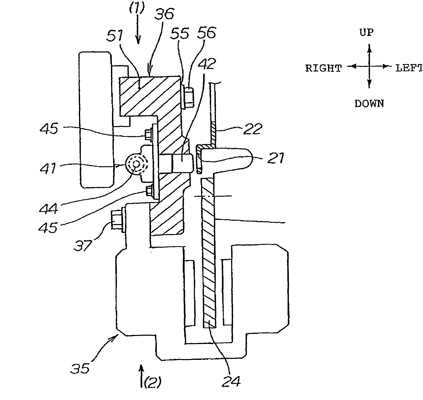
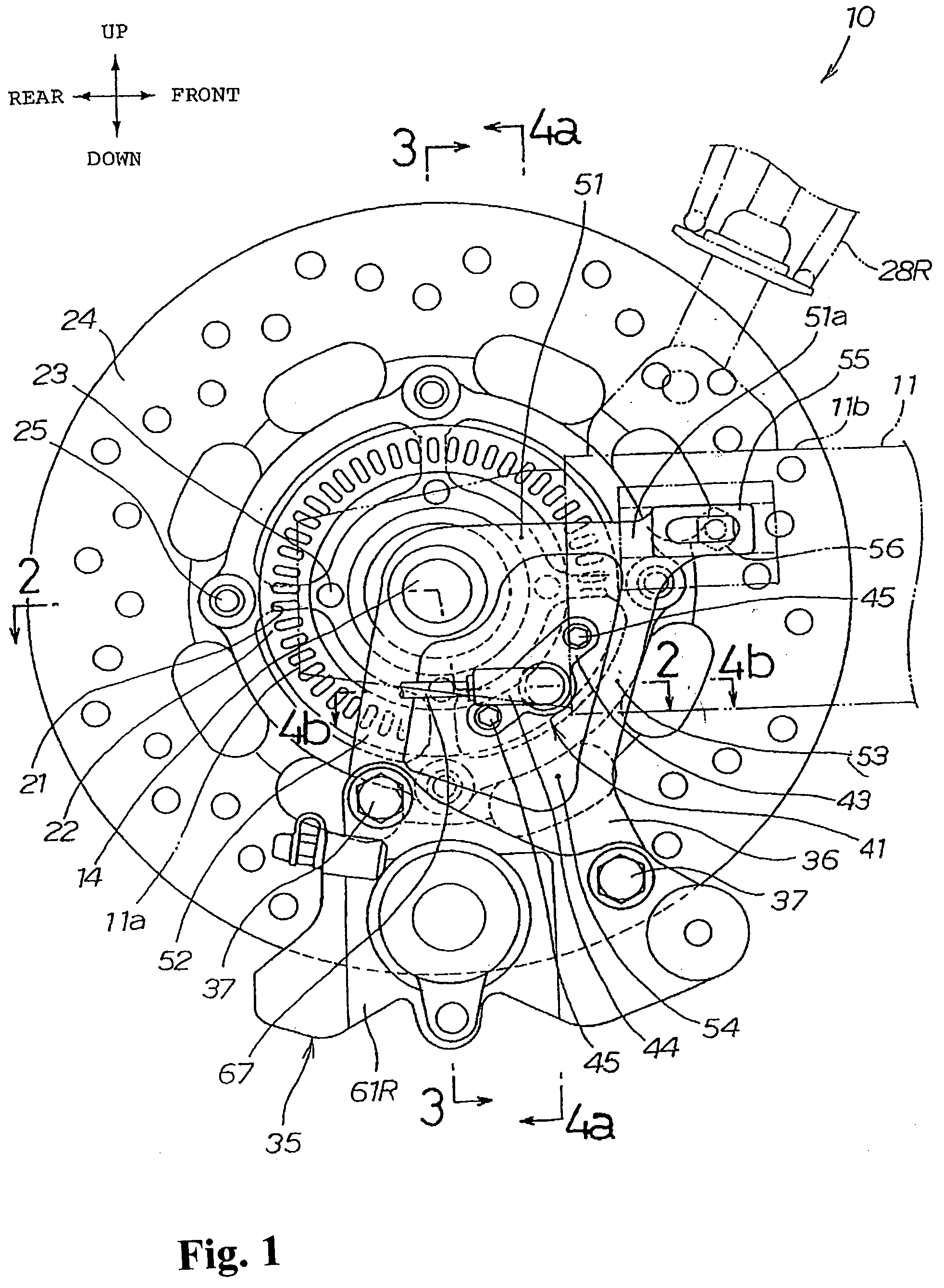
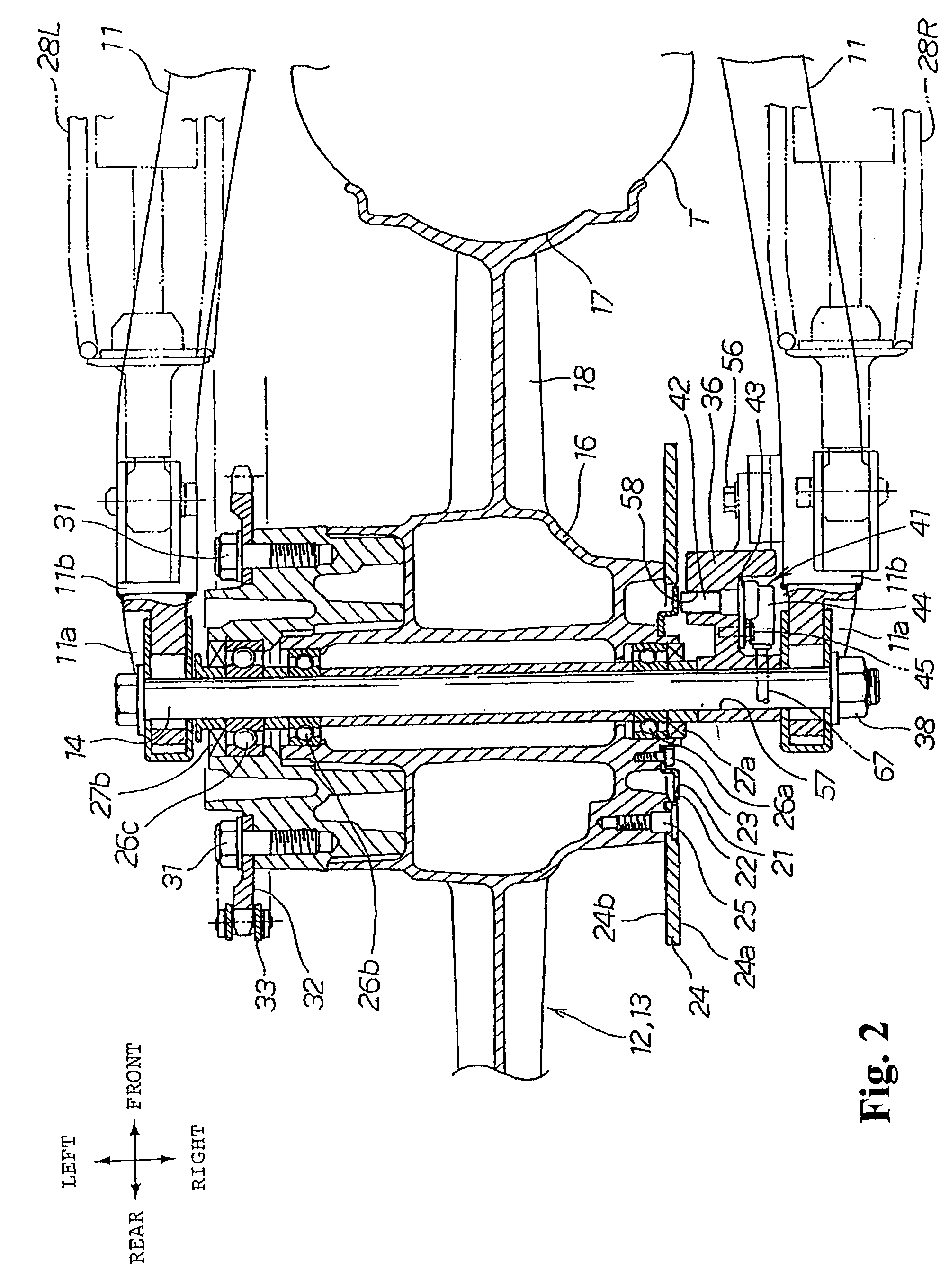
[0022]FIG. 1 is an essential part side view of a motorcycle equipped with a wheel speed sensor, FIG. 2 is a sectional view taken along line 2-2 of FIG. 1, and FIG. 3 is a sectional view taken along line 3-3. Now, description will be made by referring to FIGS. 1 to 3.

[0023]A swing arm 11 is provided at a rear part of a body frame constituting the motorcycle 10, and a rear wheel axle 14 for turnably supporting a rear wheel 13 as a wheel 12 is provided at an end part 11a of the swing arm 11. Thus, the rear wheel 13 is t...


PUM


Abstract

A motorcycle includes a swing arm swingably provided on a body frame, a wheel rotatably provided at an end part of the swing arm, a disk plate attached to the wheel, a caliper bracket provided on the body frame side of the vehicle, a disk brake caliper provided on the caliper bracket, and a wheel speed sensor attached to the caliper bracket. The wheel speed sensor is disposed between the swing arm and the wheel. The wheel speed sensor and the swing arm overlap one other in a side view of the vehicle.

Description

TECHNICAL FIELD[0001]The present invention relates to a motorcycle equipped with a wheel speed sensor for detecting the rotating speed of a wheel.BACKGROUND OF THE INVENTION[0002]A motorcycle including a disk brake caliper for applying a braking force to a wheel, a caliper bracket for fixing the disk brake caliper to the body frame side, and a wheel speed sensor attached to the caliper bracket in order to detect the rotating speed of the wheel is known. See, e.g., Japanese Patent Laid-open No. 2007-78549 (“JP '549”).[0003]In FIG. 3 of JP '549, a rear wheel 14 (the same reference symbols as in the document are used herein) is rotatably (swingably) mounted to an end part of a swing arm 12 through an axle 15, and a brake caliper 28 is mounted to the swing arm 12 through a brake caliper holder 27 extending toward the lower side. A rotation sensor 40 for detecting the rotating speed of the rear wheel 14 is mounted to the brake caliper holder 27, and a blocking wall 53 for receiving a for...

Claims


Application Information

Patent Timeline
IPC IPC(8): B60T8/72
CPCB62K19/38B60T8/329
Inventor ISHIDA, SHINICHIRONIMURA, TAISUKE
Owner HONDA MOTOR CO LTD
Why Eureka
Try Eureka