
High-performance virtual machine networking

a virtual machine and networking technology, applied in the field of virtualized computer systems, can solve the problems of introducing delay, general insufficient parameters of desired transfer,

Inactive Publication Date: 2009-07-16
VMWARE INC
View PDF17 Cites 79 Cited by
  • Summary
  • Abstract
  • Description
  • Claims
  • Application Information

AI Technical Summary

Benefits of technology

The invention provides a method for transferring data between a virtual computer and a destination over a network as a sequence of packets. The virtual computer runs on a physical host computer and includes a system software kernel and a virtual network interface device. The method involves mapping a region of memory as a shared memory region and storing incoming and outgoing packets in this shared memory region. The virtual network interface device issues an interrupt to the virtual computer when a transfer request is detected and the virtual computer dismisses the interrupt and processes the received packets. The invention also provides a mechanism for offloading interrupts in a system with multiple processors and a destination entity running on a separate processor.

Problems solved by technology

During the process of restoring the new world's state, no exceptions are allowed to take place because, if they did, the state of the new world would be inconsistent upon restoration of the state.
The “raw” data sub-sets D1, D2, D3, etc., alone are generally not enough to adequately define the parameters of a desired transfer.
Unfortunately, the known method for VM networking described above has several structural and procedural features, each of which introduces delay.

Method used


Image

  • High-performance virtual machine networking
  • High-performance virtual machine networking
  • High-performance virtual machine networking

Examples


Embodiment Construction

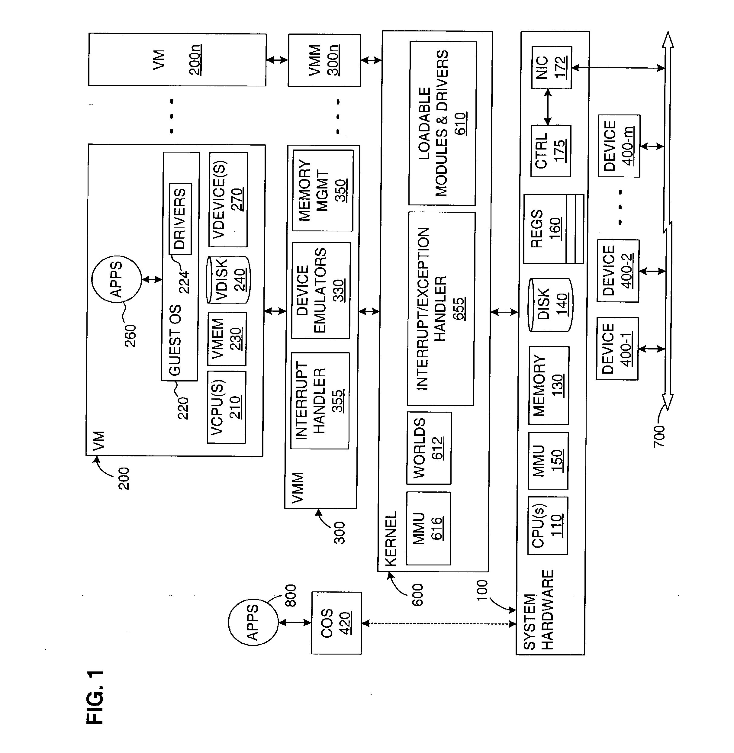
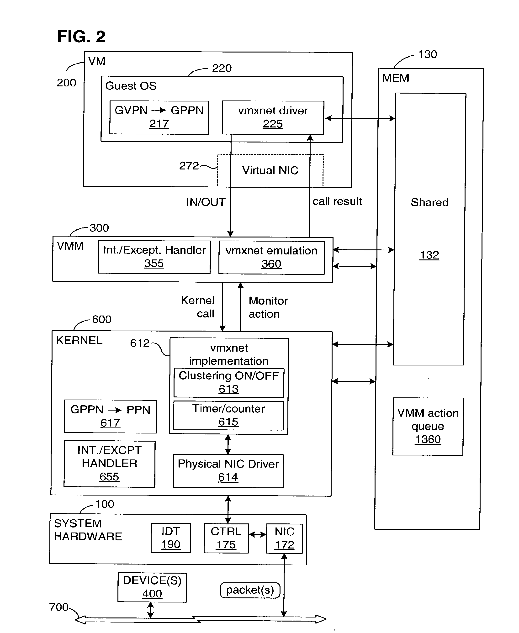
[0087]In broadest terms, two features of the invention enable it to overcome the delay-causing disadvantages of the prior art. First, to eliminate the need for host transitions, NIC drivers (one more, depending on the number of NICs included) are installed and run within the kernel 600. This allows all networking to be done by direct kernel interactions. Second, a novel virtual networking interface is provided that minimizes and, in some cases eliminates, the need for VM-to-VMM and VMM-to-kernel transitions, as well as the need to copy data. The interface according to the invention has the added advantage of simplicity and thus avoids the complexity of emulating a standard interface. These features of the invention are described below in greater detail.

[0088]In the description of the invention below, it is assumed that the system hardware 100 has the Intel x86 architecture only because this is the platform on which the ESX Server product of VMware, Inc., currently runs and it is the...


PUM


Abstract

A virtual machine (VM) runs on system hardware, which includes a physical network interface device that enables transfer of packets between the VM and a destination over a network. A virtual machine monitor (VMM) exports a hardware interface to the VM and runs on a kernel, which forms a system software layer between the VMM and the system hardware. Pending packets (both transmit and receive) issued by the VM are stored in a memory region that is shared by, that is, addressable by, the VM, the VMM, and the kernel. Rather than always transferring each packet as it is issued, packets are clustered in the shared memory region until a trigger event occurs, whereupon the cluster of packets is passed as a group to the physical network interface device. Optional mechanisms are included to prevent packets from waiting too long in the shared memory space before being transferred to the network. An interrupt offloading mechanism is also disclosed for use in multiprocessor systems such that it is in most cases unnecessary to interrupt the VM in order to request a VMM action, and the need for VMM-to-kernel context transitions is reduced.

Description

CROSS-REFERENCE TO RELATED APPLICATIONS[0001]This application is a continuation of U.S. patent application Ser. No. 10 / 383,702, filed Mar. 7, 2003, which is a continuation-in-part of U.S. patent application Ser. No. 09 / 877,378, filed Jun. 8, 2001, now U.S. Pat. No. 6,961,941.BACKGROUND OF THE INVENTION[0002]1. Field of the Invention[0003]This invention relates to virtualized computer systems, in particular, to a system and method for improving the performance of network transfers to and from a virtual machine.[0004]2. Description of the Related Art[0005]The advantages of virtual machine technology have become widely recognized. Among these advantages is the ability to run multiple virtual machines on a single host platform. This makes better use of the capacity of the hardware, while still ensuring that each user enjoys the features of a “complete,” isolated computer.[0006]General Virtualized Computer System[0007]As is well known in the field of computer science, a virtual machine (...

Claims


Application Information

Patent Timeline
Patent Type & Authority Applications(United States)
IPC IPC(8): G06F13/20G06F9/455G06F9/00
CPCG06F9/45533G06F9/4812G06F9/546G06F9/45504G06F9/455G06F2009/45595G06F13/24G06F9/45558G06F9/542G06F9/544
Inventor NELSON, MICHAEL
Owner VMWARE INC
Learn More