Method of detecting fine surface defects

a technology of fine surface defects and surface, applied in the direction of material analysis using wave/particle radiation, x/gamma/cosmic radiation measurement, instruments, etc., can solve the problems of difficult to consistently apply penetrant on the subject, penetrant is subject to contamination, penetrant on the surface, etc., to improve the inspection efficiency of fine surface defects

Inactive Publication Date: 2009-07-16
NAM SANG HEE +5
View PDF3 Cites 7 Cited by
  • Summary
  • Abstract
  • Description
  • Claims
  • Application Information

AI Technical Summary

Benefits of technology

[0010]Accordingly, the present invention has been made to solve the above problems occurring in the prior art, and an object of the present invention is to provide a method of detecting fine surface defects which can overcome the problems with the conventional methods, such as surface contamination, the difficulty in realizing uniform application of a penetrant on a subject, the limitations on the dwelling time of the penetrant and the testing temperature (surface temperature of the subject: 16˜50° C.) thereof, and the contamination of the penetrant, and which can improve the inspection efficiency of fine surface defects.

Problems solved by technology

However, the method of spraying a penetrant on the surface defects in a subject using a sprayer is problematic in that the penetrant is also sprayed on unwanted areas, and it is not easy to consistently apply the penetrant on the subject.
Further, the method is problem in that the dwelling time of the penetrant and the testing temperature (surface temperature of the subject: 16˜50° C.) thereof are limited, and the penetrant is subject to contamination.
Similarly, the method of spreading a penetrant on the surface defects in a subject using a predetermined brush is also problematic in that it is not easy to consistently apply the penetrant on the subject.
Therefore, conventional methods of detecting fine surface defects are problematic in that the inspection efficiency of fine surface defects is low.

Method used


Image

  • Method of detecting fine surface defects
  • Method of detecting fine surface defects

Examples


Embodiment Construction

[0016]Hereinafter, the present invention will be described in detail with reference to the attached drawing. In the description of the present invention, when it is determined that the technical point of the present invention would be made unclear by a detailed description of commonly-known technologies, such detailed description of commonly-known technologies will be omitted.

[0017]Further, the terms used herein are defined in consideration of the functions in the present invention, and can be changed depending on the intentions of users, or precedents. Therefore, the definition of the following terms must be understood based on the entire content of the specification of the present invention.

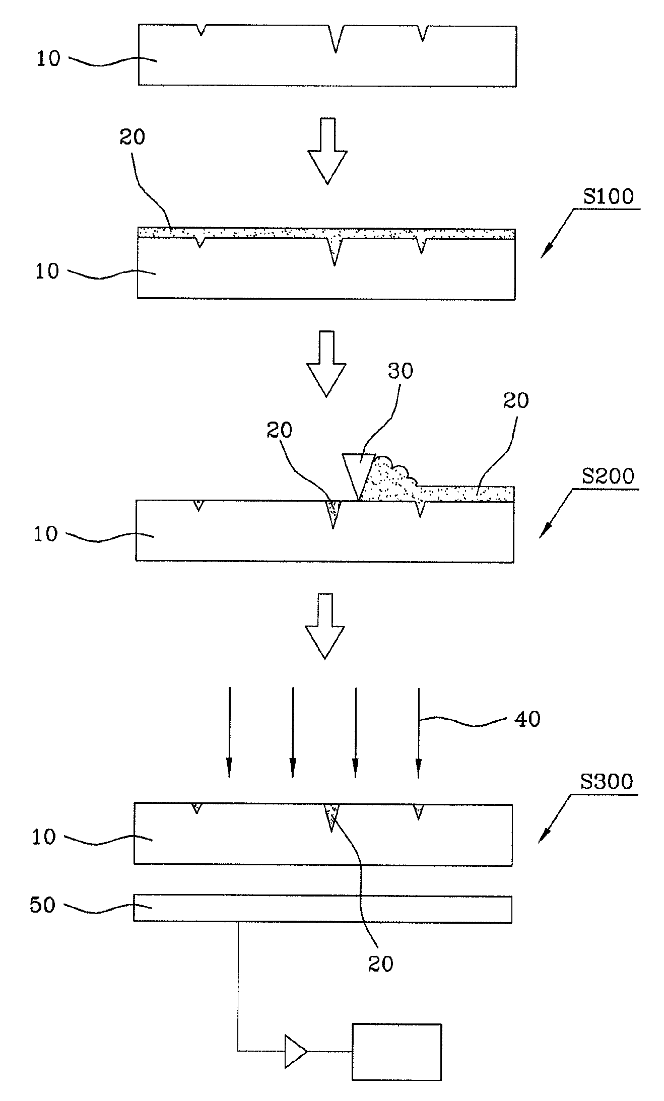
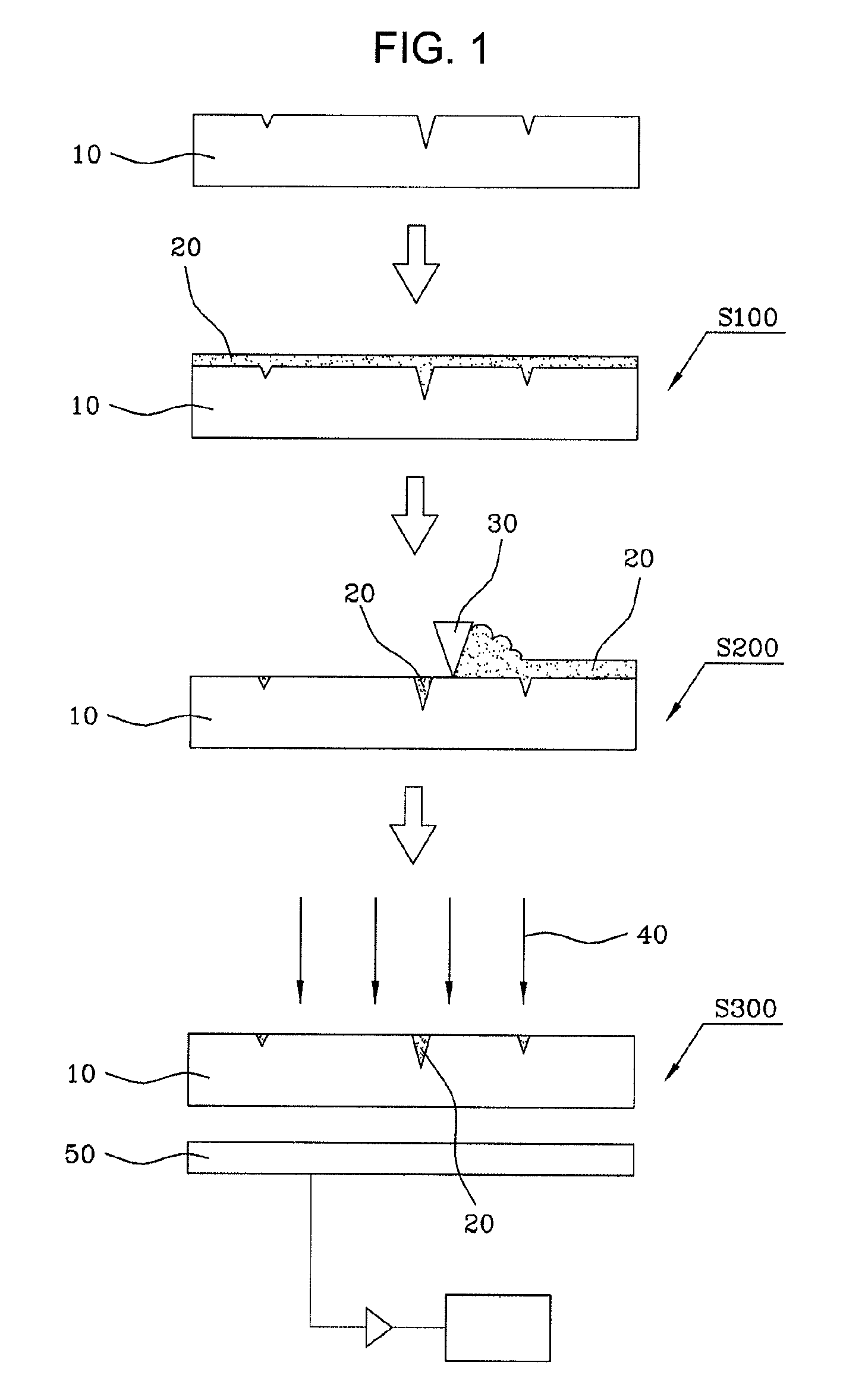
[0018]FIG. 1 is a process view showing a method of detecting fine surface defects according to the present invention.

[0019]As shown in FIG. 1, the method of detecting fine surface defects according to the present invention includes the steps of applying (S100), squeegeeing (S200) and detecting ...


PUM


Abstract

Disclosed herein is a method of detecting fine surface defects, including: applying nano phosphor paste on a surface of a subject; squeegeeing the surface of the subject such that the nano phosphor paste remains only in defects in the subject; and detecting the fine defects in the subject by placing the subject over a light detection plate, irradiating the subject with a light source, and then determining that light-emitting portions detected using the light detection plate are defects in the subject. The method of detecting fine surface defects is advantageous in that the problems with the conventional methods, such as surface contamination, the difficulty in realizing uniform application of a penetrant on a subject, the limitations on the dwelling time of the penetrant and the testing temperature (surface temperature of the subject: 16˜50° C.) thereof, and the contamination of the penetrant, can be overcome, and in that the incidence of inspection errors is decreased, and the time and cost of inspection are reduced, thus improving the production yield of the subject.

Description

BACKGROUND OF THE INVENTION[0001]1. Field of the Invention[0002]The present invention relates to a method of detecting fine surface defects, and, more particularly, to a method of detecting fine surface defects formed on the surface of spectacles, lenses, flat glass and TFT arrays used for radiation detectors using nano phosphor (that is, nano fluorescent material), by which defects that cannot be visually observed are detected, so that the yield of products increases and the inspection time thereof decreases, thereby improving productivity.[0003]2. Description of the Related Art[0004]Conventionally, a liquid penetrant examination method has been used as a method of detecting fine surface defects. This liquid penetrant examination method, which is in the field of nondestructive inspection, is a method of evaluating the quality of products by examining the position, size and patterns of the defects formed on the products, including the processes of applying a penetrant on the surface...

Claims


Application Information

Patent Timeline
IPC IPC(8): G01N23/223G01N33/28
CPCG01N21/91B82Y30/00G01B11/30G01N21/892G01N2021/8918
Inventor NAM, SANG HEEKANG, SANG SIKCHO, SUNG HOKWON, CHOULYUN, MIN SEOKOH, KYUNG MIN
Owner NAM SANG HEE
Why Eureka
Try Eureka