
Three-axial acceleration sensor inspection device and method of inspecting three-axial acceleration sensor

a three-axial acceleration sensor and inspection device technology, applied in the direction of speed/acceleration/shock measurement, speed/acceleration/shock measurement, testing/calibration of speed/acceleration/shock measurement devices, etc., can solve problems such as deteriorating inspection efficiency, and achieve the effect of reducing rotational radius, improving inspection efficiency, and reducing the size of the three-axial acceleration sensor inspection devi

Inactive Publication Date: 2007-12-06
LAPIS SEMICON CO LTD
View PDF7 Cites 38 Cited by
  • Summary
  • Abstract
  • Description
  • Claims
  • Application Information

AI Technical Summary

Benefits of technology

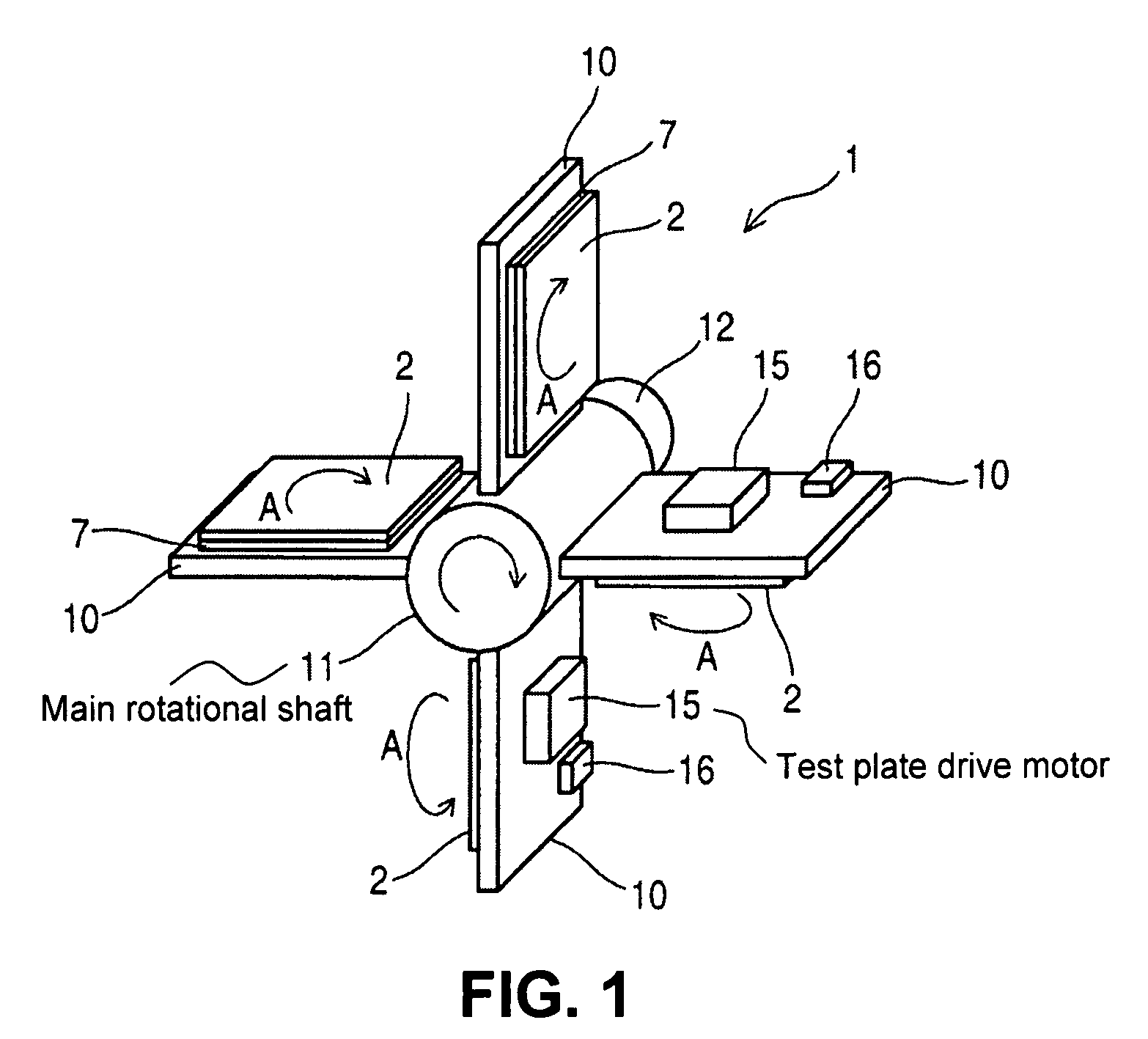
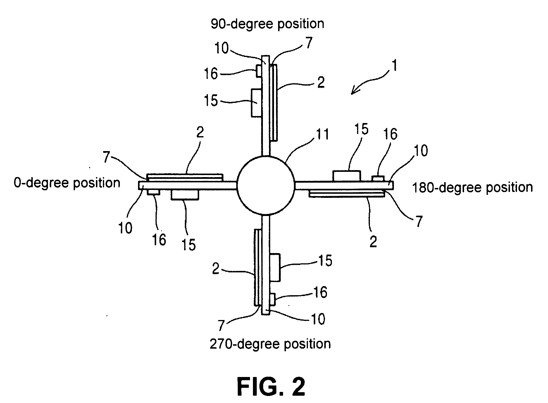
The present invention provides a three-axial acceleration sensor inspection device that can inspect a three-axial acceleration sensor that detects acceleration components in three axes crossing perpendicularly with each other and outputs acceleration component signals. The device includes a test plate, a supporting plate, and a main rotational shaft. The supporting plate is arranged radially around the main rotational shaft along a radius direction of the main rotational shaft, and is disposed at each of at least four locations with an equal angular interval along a circumferential direction of the main rotational shaft. The device allows for simultaneous inspection of the three-axial acceleration sensors at the four locations in each axial position, reducing inspection time and improving efficiency. The test plate rotates around the main rotational shaft in a reduced rotational radius, reducing the size of the inspection device.

Problems solved by technology

In short, it takes a long period of time to inspect a large number of three-axial acceleration sensors, thereby deteriorating inspection efficiency.

Method used


Image

  • Three-axial acceleration sensor inspection device and method of inspecting three-axial acceleration sensor
  • Three-axial acceleration sensor inspection device and method of inspecting three-axial acceleration sensor
  • Three-axial acceleration sensor inspection device and method of inspecting three-axial acceleration sensor

Examples


Embodiment Construction

[0019]Hereunder, embodiments of the present invention will be explained with reference to the accompanying drawings.

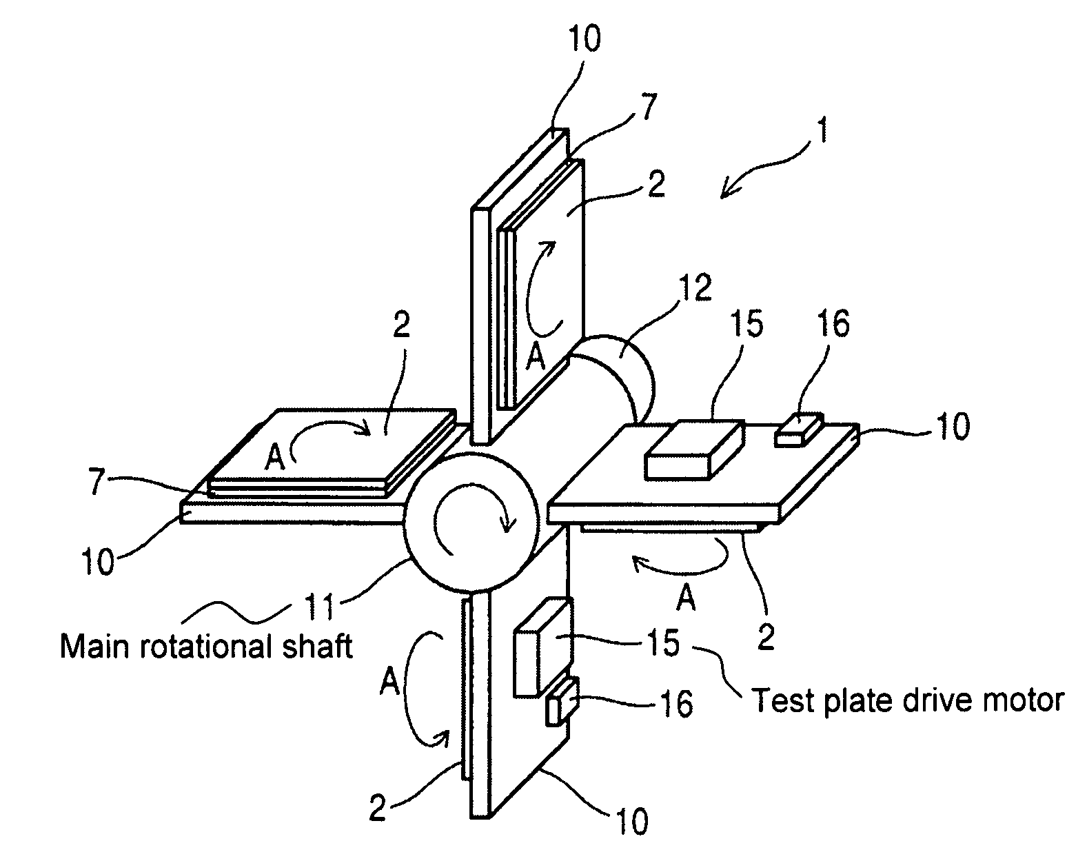
[0020]FIG. 1 is a schematic perspective view showing a three-axial acceleration sensor inspection device 1 according to an embodiment of the present invention. FIG. 2 is a schematic front view showing the three-axial acceleration sensor inspection device 1 according to the embodiment of the present invention. FIG. 3 is a schematic perspective view showing a three-axial acceleration sensor inspection system 20 according to the embodiment of the present invention. FIG. 4 is a schematic view showing a test plate 7 and a test tray 2 according to the embodiment of the present invention.

[0021]As shown in FIG. 4, the test tray 2 is a container for collectively retaining one series of three-axial acceleration sensors 3 all together, and is provided with a plurality of receptacle portions 4 each for retaining the three-axial acceleration sensor 3 and fixing members 5 for holdin...


PUM


Abstract

A three-axial acceleration sensor inspection device is provided for inspecting a three-axial acceleration sensor that detects acceleration components in three axes crossing perpendicularly with each other and outputs acceleration component signals. The three-axial acceleration sensor inspection device includes a test plate for mounting the three-axial acceleration sensor thereon; a supporting plate for supporting and rotating the test plate; a main rotational shaft for rotating the supporting plate. The supporting plate is arranged radially around the main rotational shaft along a radius direction of the main rotational shaft, and is disposed at each of at least four locations with an equal angular interval along a circumferential direction of the main rotational shaft.

Description

BACKGROUND OF THE INVENTION AND RELATED ART STATEMENT[0001]The present invention relates to a three-axial acceleration sensor inspection device for inspecting a three-axial acceleration sensor that detects acceleration components in three axes crossing perpendicularly with each other to output an acceleration component signal. Further, the present invention relates to a method of inspecting a three-axial acceleration sensor.[0002]In a conventional three-axial acceleration sensor inspection device, a main rotational shaft is provided for rotating a support plate having an L character shape. A test plate drive motor is attached to the support plate for rotating a test plate arranged in parallel to a shaft axis of the main rotational shaft. A plurality of three-axial acceleration sensors is mounted on the test plate.[0003]When the three-axial acceleration sensors are inspected, the main rotational shaft rotates the test plate by 180 degrees to measure an acceleration component in a Z d...

Claims


Application Information

Patent Timeline
Patent Type & Authority Applications(United States)
IPC IPC(8): G01P21/00G01P15/18
CPCG01P21/00G01P15/18
Inventor KAMIYA, ISAO
Owner LAPIS SEMICON CO LTD
Learn More